Eureka AIR delivers breakthrough ideas for toughest innovation challenges, trusted by R&D personnel around the world.

Elliptical resonance modal piezoelectric type MEMS circular ring gyroscope

A resonant mode, gyroscope technology, applied in gyroscope/steering sensing equipment, gyro effect for speed measurement, instruments, etc., can solve the problem of low mechanical sensitivity and detection sensitivity, achieve good structural symmetry, reduce resonance Frequency difference, effect of reducing thermoelastic loss

Active Publication Date: 2020-04-10
武汉敏声新技术有限公司
View PDF13 Cites 4 Cited by
  • Summary
  • Abstract
  • Description
  • Claims
  • Application Information

AI Technical Summary

Problems solved by technology

However, the existing piezoelectric MEMS gyroscopes have low mechanical sensitivity and detection sensitivity.

Method used


Image

  • Elliptical resonance modal piezoelectric type MEMS circular ring gyroscope
  • Elliptical resonance modal piezoelectric type MEMS circular ring gyroscope
  • Elliptical resonance modal piezoelectric type MEMS circular ring gyroscope

Examples


Embodiment 1

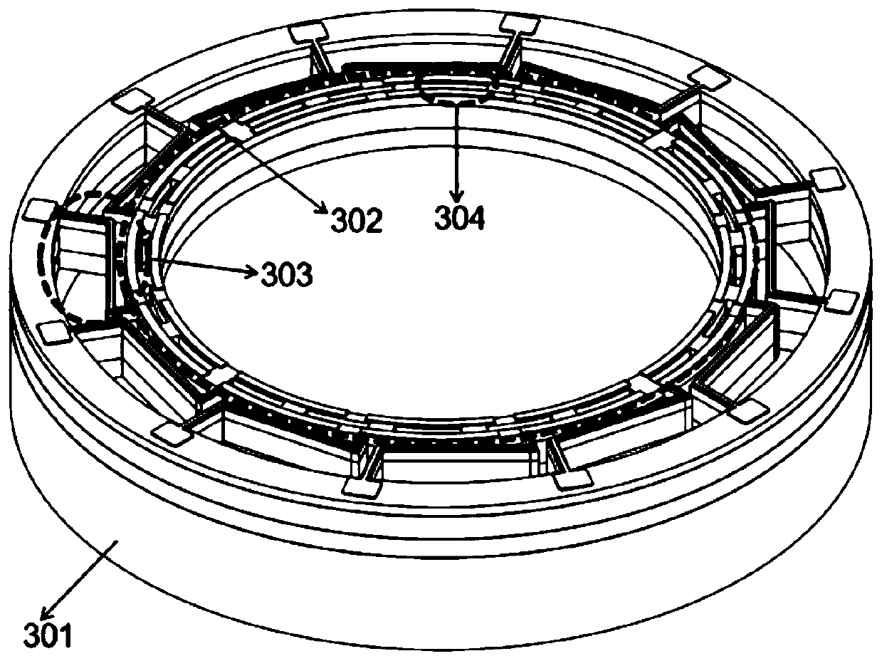
[0033] Such as figure 1 , figure 2 with Figure 5 As shown, an elliptical resonance mode piezoelectric MEMS ring gyroscope includes a substrate 101 with a concave cavity, a ring resonator 103 and a Z-shaped beam 102 suspended above the concave cavity, and twelve Z-shaped beams 102 are evenly distributed along the outer side of the ring resonator 103, and the ring resonator 103 is connected to the peripheral fixed support structure through the Z-shaped beam 102, and the peripheral fixed support structure is fixed to the substrate 101, and the outer circle on the top surface of the ring resonator 103 and The central circle between the inner circles is the reference circle, and forty heat insulation grooves 104 (obtained by etching) are uniformly distributed along the reference circle along the thickness direction, and the top electrode of the ring resonator 103 is differentiated along the inside and outside of the reference circle. Arrangement (the insulation groove 104 is se...

Embodiment 2

[0043] Such as Figure 3 to Figure 5 As shown, the structure of the second embodiment is basically the same as that of the first embodiment, the difference is that the ring resonator 303 includes a silicon oxide layer 401, a heavily doped silicon structure layer 402, a piezoelectric material layer 403 and The top electrode layer 404, wherein the heavily doped silicon structure layer 402 serves as the bottom electrode layer. The silicon structure layer 402 can be heavily doped to reduce the temperature coefficient of the elastic constant of the silicon material, realize passive temperature compensation, and further improve the temperature stability of the ring gyroscope.

[0044] In Embodiment 1 and Embodiment 2, Z-shaped beams (102 and 302) are used as the fixed-support beams. In fact, the fixed-support beams can also be straight beams, T-shaped beams, and the like.

[0045] In Embodiment 1 and Embodiment 2, the heat-insulation grooves (104 and 304) are all arc-shaped grooves...


PUM


Abstract

The invention discloses an elliptical resonance modal piezoelectric type MEMS circular ring gyroscope, which comprises a substrate provided with a concave cavity, and a circular ring harmonic oscillator and clamped beams are suspended above the concave cavity; the clamped beams are uniformly distributed along the outer side of the circular ring harmonic oscillator; the circular ring harmonic oscillator is connected with a peripheral clamped structure by means of the clamped beams, the peripheral clamped structure is fixed to the substrate, a central circle between an outer circle and an innercircle on the top surface of the circular ring harmonic oscillator is used as a reference circle, heat insulation grooves penetrating through the thickness direction are uniformly distributed along the reference circle, and top electrodes of the circular ring harmonic oscillator are differentially arranged along the inner side and the outer side of the reference circle. The elliptical resonance modal piezoelectric type MEMS circular ring gyroscope is simple in structure, small in size, easy to manufacture in batches and high in mechanical sensitivity.

Description

technical field [0001] The invention belongs to the field of micromechanical sensors, in particular to an elliptical resonance mode piezoelectric MEMS ring gyroscope. Background technique [0002] Gyroscope refers to a detection device that measures the rotation angle or angular velocity of the platform. It plays a very important role in the fields of modern navigation, aerospace, aviation and national defense technology. It is of great significance to promote industrial development and strengthen national defense security. With the emergence of micro-electro-mechanical systems (Micro-Electro-Mechanical System, MEMS), gyroscopes have begun to develop in the direction of small size, high precision, low power consumption and resistance to interference from harsh environments. Gyroscopes based on MEMS technology have the advantages of small size, low power consumption, and high precision. Therefore, MEMS gyroscopes have become an important direction for the development of gyros...

Claims


Application Information

Patent Timeline
Patent Type & Authority Applications(China)
IPC IPC(8): G01C19/5656
CPCG01C19/5656
Inventor 陈浩然吴国强
Owner 武汉敏声新技术有限公司
Why Eureka
Eureka Blog
Learn More