
System passivity based underactuation bridge crane anti-interference anti-swing method

A bridge crane, passive technology, applied in the direction of load suspension components, transportation and packaging, etc., can solve the problems of complex dynamic model of the crane system, frequent casualties, high degree of under-actuation, etc., to achieve improved transient control High performance, strong anti-interference ability, and fast positioning effect

Active Publication Date: 2020-04-10
WUHAN UNIV OF SCI & TECH
View PDF6 Cites 10 Cited by
  • Summary
  • Abstract
  • Description
  • Claims
  • Application Information

AI Technical Summary

Problems solved by technology

However, the effect of these operations is not ideal, and the following shortcomings are reflected: 1) The positioning accuracy is poor, and the trolley needs to be adjusted repeatedly before reaching the target position; 2) The operation efficiency is low, and the effect of eliminating the swing is poor; Operators have high requirements and need long-term skill training and continuous experience accumulation; 4) Long-term continuous work is easy to cause fatigue, resulting in misoperation and frequent casualties; 5) In special applications, such as nuclear material transportation, etc., Cannot be operated manually
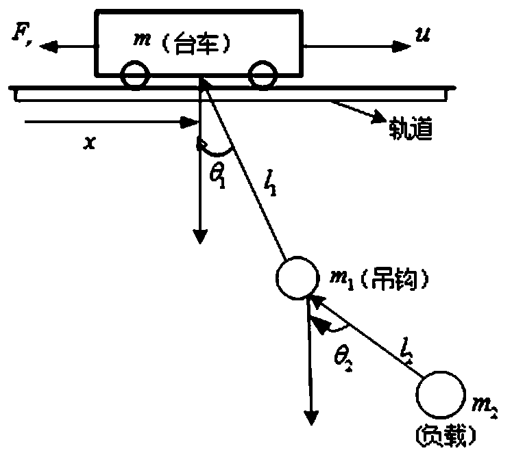
The overhead crane system is a typical underactuated system, most of the existing control methods only consider the single-stage swing characteristics of the crane system, but in many cases: 1) When the hook mass is similar to the load mass and cannot be ignored ;2) When the distribution of load mass is uneven and the size is too large to be regarded as a mass point, the crane system will show double pendulum characteristics
When the double pendulum characteristic occurs, the load will swing around the hook, resulting in a more complex dynamic model of the crane system, higher coupling between states, and a higher degree of underactuation. great challenge

Method used


Image

  • System passivity based underactuation bridge crane anti-interference anti-swing method
  • System passivity based underactuation bridge crane anti-interference anti-swing method

Examples


Embodiment Construction

[0022] The following are specific embodiments of the present invention and in conjunction with the accompanying drawings, the technical solutions of the present invention are further described, but the present invention is not limited to these embodiments.

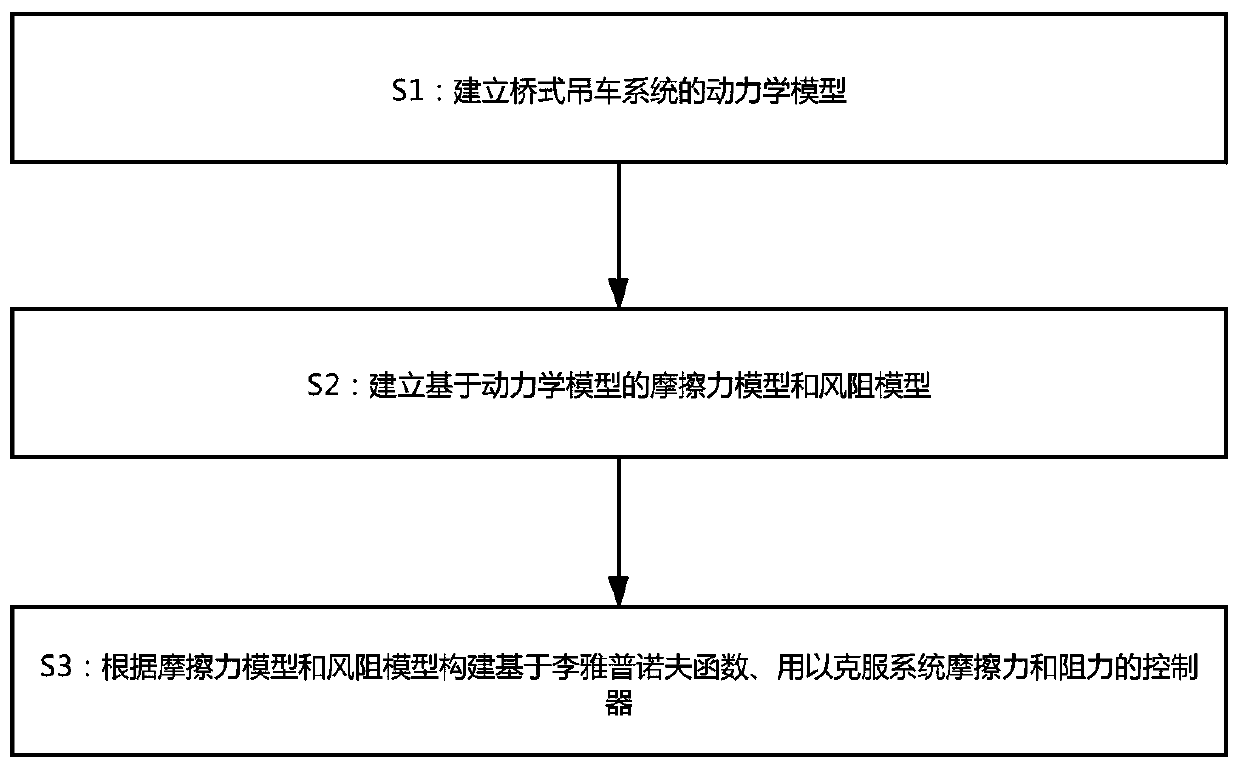
[0023] see figure 1 with figure 2 , the anti-jamming and anti-swing method of an underactuated overhead traveling crane based on system passivity in this embodiment includes the following steps:

[0024] S1: Establish the dynamic model of the overhead crane system;

[0025] S2: Establish a friction model and a wind resistance model based on the dynamic model;

[0026] S3: Construct a controller based on the Lyapunov function to overcome the friction and resistance of the system according to the friction model and the wind resistance model.

[0027] Here, the dynamic model of the two-stage pendulum system of the overhead crane is first established, and the friction model and wind resistance model of the system are estab...


PUM


Abstract

The invention provides a system passivity based underactuation bridge crane anti-interference anti-swing method and belongs to the technical field of bridge crane anti-swing. The system passivity based underactuation bridge crane anti-interference anti-swing method comprises the following steps of S1, establishing a dynamical model of a bridge crane system; S2, establishing a friction force modeland a wind resistance model based on the dynamical model; and S3, constructing a controller based on the lyapunov function and used for overcoming system friction force and resistance according to thefriction force model and the wind resistance model. Through the system passivity based underactuation bridge crane anti-interference anti-swing method, the friction force and resistance in the systemcan be overcome, quick positioning of the crane system is realized, and swing of the system is effectively inhibited; moreover, the system is high in anti-interference capability and has high robustness. As anti-swing positioning of a trolley is realized well, the transient state control performance of the system is effectively improved.

Description

technical field [0001] The invention belongs to the technical field of swing prevention for bridge cranes, and relates to an anti-jamming and swing prevention method for underactuated bridge cranes based on system passivity. Background technique [0002] Among all kinds of cranes, the bridge crane is the most widely used. As with other cranes, the main goal of overhead crane control is the fast and accurate delivery of loads in the shortest possible time. As an underactuated system, the bridge crane has simple algorithm design, fewer controllers and lower cost. However, with the movement of the trolley, the crane will have instability problems due to the swing phenomenon of the load. The relationship between trolley and load swing is non-linear and highly coupled. In addition, the load swing caused by external disturbances (such as wind, etc.) will not only reduce the overall efficiency, affect the precise placement of the load during the lifting process, but may also cau...

Claims


Application Information

Patent Timeline
Patent Type & Authority Applications(China)
IPC IPC(8): B66C13/06B66C13/48
CPCB66C13/06B66C13/48
Inventor 柴琳刘惠康鄢梦伟孙博文皮瑶李倩
Owner WUHAN UNIV OF SCI & TECH
Learn More