Printer layered paper receiving mechanism and working method thereof

A paper splicing mechanism and printer technology, applied in the directions of printing device, printing, pile separation, etc., can solve the problems of easy damping of paper, inconvenient maintenance, inconvenient intelligent adjustment, etc., to avoid accumulation, increase friction, and ensure the printing effect. Effect

Inactive Publication Date: 2020-04-10
重庆珏顺科技有限公司
View PDF12 Cites 1 Cited by
  • Summary
  • Abstract
  • Description
  • Claims
  • Application Information

AI Technical Summary

Problems solved by technology

The print output management system controls the coordinated operation of the printer and the action system. The action system controls the up and down movement of the output box. The output box has a multi-layer structure, and each layer corresponds to a user; The location of the multi-layer structure of the output box, but it is inconvenient to intelligently adjust, and it is inconvenient to damage and repair. At the same time, the traditional printer stores paper inside for printing. The paper is easy to be damp after a long time, and it is easy to affect the printing effect of the paper.

Method used


Image

  • Printer layered paper receiving mechanism and working method thereof
  • Printer layered paper receiving mechanism and working method thereof
  • Printer layered paper receiving mechanism and working method thereof

Examples


Embodiment Construction

[0030] The following will clearly and completely describe the technical solutions in the embodiments of the present invention with reference to the accompanying drawings in the embodiments of the present invention. Obviously, the described embodiments are only some, not all, embodiments of the present invention.

[0031] In describing the present invention, it should be understood that the terms "upper", "lower", "front", "rear", "left", "right", "top", "bottom", "inner", " The orientation or positional relationship indicated by "outside", etc. is based on the orientation or positional relationship shown in the drawings, and is only for the convenience of describing the present invention and simplifying the description, rather than indicating or implying that the referred device or element must have a specific orientation, so as to Specific orientation configurations and operations, therefore, are not to be construed as limitations on the invention.

[0032] refer to Figure ...


PUM


Abstract

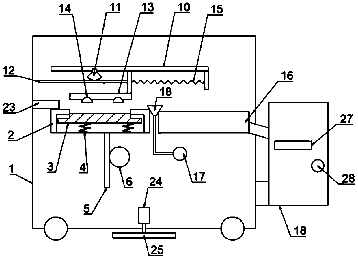
The invention discloses a printer layered paper receiving mechanism. The printer layered paper receiving mechanism comprises a machine body, wherein a plurality of rolling wheels are arranged on the lower side wall of the machine body, a supporting disc is arranged in the machine body, and a baffle located on the upper side of the supporting disc is fixed to the inner wall of the machine body; a supporting plate slides in the supporting disc, and a telescopic spring is fixed between the supporting plate and the inner bottom wall of the supporting disc; a rack plate I is fixed to the lower sidewall of the supporting disc, and a gear I meshed with the rack plate I is arranged in the machine body; and a feeding box located on one side of the supporting disc is further arranged on the machinebody, a fixing plate located on the upper side of the supporting disc and the upper side of the feeding box is fixed in the machine body, a sliding groove is formed in the lower side wall of the fixing plate, and a sliding plate slides in the sliding groove. According to the printer layered paper receiving mechanism, through transfer of paper and contact between hot air flow and the paper, the paper is dried and baked, so that the subsequent printing effect is guaranteed; and the positions of a plurality of paper receiving plates are adjusted through rotation of a rotary button, so that printouts are placed separately, and accumulation is avoided.

Description

technical field [0001] The invention relates to the technical field of printers, in particular to a layered paper splicing mechanism of a printer and a working method thereof. Background technique [0002] A printer is one of the output devices of a computer, which is used to print computer processing results on related media. There are three indicators to measure the quality of a printer: printing resolution, printing speed and noise. There are many types of printers. According to whether the printing element hits the paper, it can be divided into impact printers and non-impact printers. According to the structure of printing characters, it can be divided into full-size character printers and dot-matrix character printers. According to the way a line of characters is formed on paper, it can be divided into serial printers and line printers. According to the technology adopted, it is divided into printers such as cylindrical, spherical, inkjet, thermal, laser, electrostat...

Claims


Application Information

Patent Timeline
Patent Type & Authority Applications(China)
IPC IPC(8): B65H3/08B65H1/12B41J11/00
CPCB41J11/002B65H1/12B65H3/0816B65H2701/1131
Inventor 周玉杰刘冬生杨大君
Owner 重庆珏顺科技有限公司
Why Eureka
Try Eureka