A device for workpiece movement

A technology of workpiece movement and moving seat, which is applied in the field of workpiece movement devices, can solve the problems of inability to break the vacuum of the suction cup, limit the direction of ventilation, and limit the transfer range, and achieve the effects of convenient implementation, reduced energy consumption, and convenient use

Active Publication Date: 2021-08-27
广东创智智能装备有限公司
View PDF0 Cites 0 Cited by
  • Summary
  • Abstract
  • Description
  • Claims
  • Application Information

AI Technical Summary

Problems solved by technology

[0002] At present, in order to improve the suction force, some suction cups on the market are equipped with a suction one-way valve. After the user puts the suction cup close to the adsorbed part, connect the suction pump with the suction one-way valve on the suction cup so that the suction cup will be sucked into the suction chamber. After the gas is pumped out, the pumping one-way valve is automatically closed, and the adsorption effect is better. However, the pumping one-way valve restricts the ventilation direction, and the air supply from the outside to the existing pumping one-way valve cannot break the vacuum of the suction cup. If the user wants to separate the suction cup from the adsorbed part, he can only adopt other methods, such as vigorously prying the suction cup with a knife to break the vacuum, or setting other vacuum breaking structures on the suction cup, which is more troublesome to implement and not suitable for some occasions. application
[0003] In addition, in the existing continuous movement, the transfer line or fixture is mainly used to transfer the workpiece, but it is not convenient to transfer the workpiece by vacuum suction cup, because the vacuum suction cup needs to be connected with a vacuum device, and its transfer range is limited

Method used


Image

  • A device for workpiece movement
  • A device for workpiece movement
  • A device for workpiece movement

Examples


Embodiment Construction

[0024] The features of the present invention and other relevant features are described in further detail below through the embodiments, so as to facilitate the understanding of those skilled in the art:

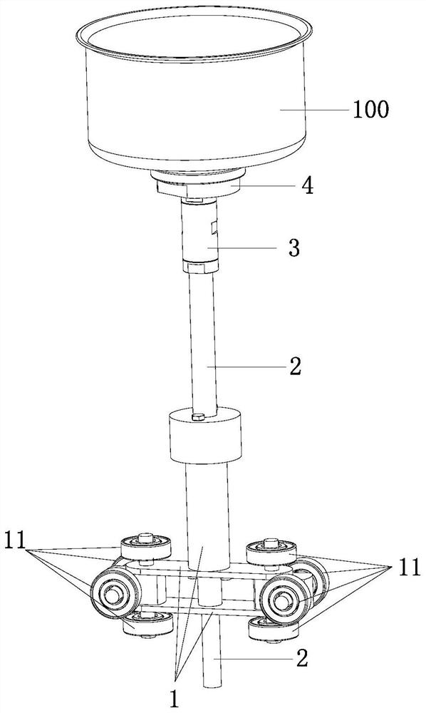
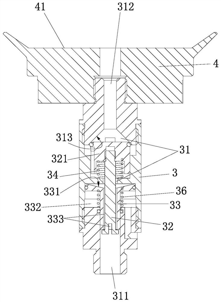
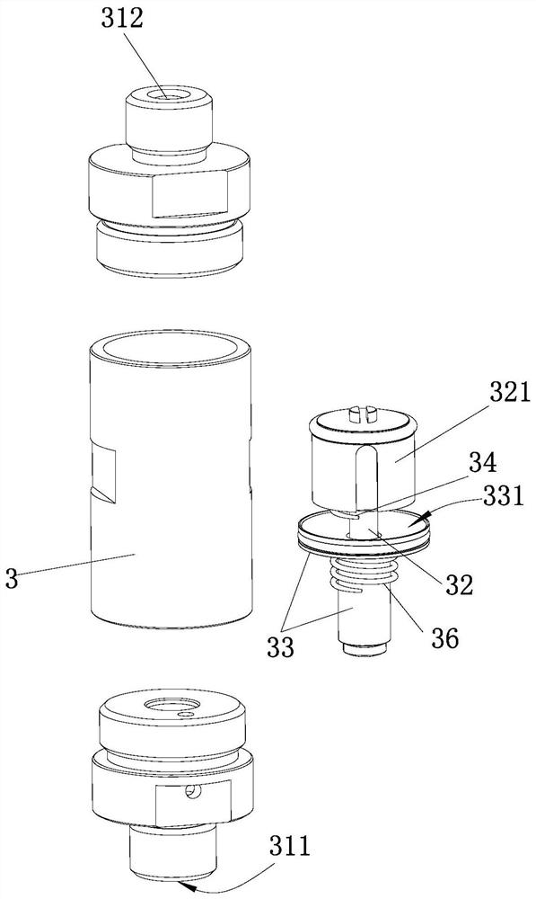
[0025] Such as Figure 1 to Figure 3 As shown, a device for moving workpieces includes a moving base 1, on which a vertical pipe 2 capable of rotating around a vertical axis is connected, and the upper end of the vertical pipe 2 is connected with a suction valve 3 through a connecting valve 3. The suction cup 4 that holds the workpiece 100, the upper end of the connection valve 3 communicates with the adsorption surface / adsorption chamber 41 of the suction cup 4, and the connection valve (3) is provided with an automatic sealing and suction device for automatically closing the suction cup (4) after being vacuumized. A valve assembly that opens automatically when the air supply breaks the vacuum.

[0026] As mentioned above, when specifically vacuuming, the external vacuum de...


PUM


Abstract

The invention discloses a device for workpiece movement, the connecting valve is provided with a valve assembly for automatically closing after the suction cup is vacuumed, so that the standpipe can be disconnected from the external vacuum device after the suction cup is vacuumed The connection facilitates the movement of the device and transfers the workpiece through the suction cup; in addition, when the air supply breaks the vacuum, since the valve assembly can be opened automatically, it is convenient for the external air supply device to send air into the suction cup through the vertical pipe and the connecting valve, and the vacuum breaker Convenient; in addition, because the standpipe can rotate relative to the movable seat around the vertical axis, that is, the suction cup on the standpipe can also rotate relative to the movable seat, which is suitable for the situation that the workpiece needs to rotate in some occasions.

Description

technical field [0001] The invention relates to a device for workpiece movement. Background technique [0002] At present, in order to improve the suction force, some suction cups on the market are equipped with a suction one-way valve. After the user puts the suction cup close to the adsorbed part, connect the suction pump with the suction one-way valve on the suction cup so that the suction cup will be sucked into the suction chamber. After the gas is pumped out, the pumping one-way valve is automatically closed, and the adsorption effect is better. However, the pumping one-way valve restricts the ventilation direction, and the air supply from the outside to the existing pumping one-way valve cannot break the vacuum of the suction cup. If the user wants to separate the suction cup from the adsorbed part, he can only adopt other methods, such as vigorously prying the suction cup with a knife to break the vacuum, or setting other vacuum breaking structures on the suction cup...

Claims


Application Information

Patent Timeline
Patent Type & Authority Patents(China)
IPC IPC(8): B65G47/91
CPCB65G47/914
Inventor 严长志许仕建
Owner 广东创智智能装备有限公司
Why Eureka
Try Eureka