
Vehicle-mounted display screen mounting structure

A technology for installation structure and display screen, which is applied to vehicle components, transportation and packaging, etc., can solve the problems of affecting work efficiency, affecting the appearance, blocking the sight of locking screws, etc., achieving the reduction of frequent rotation of the cover, simple and practical structural design, and improved The effect of work efficiency

Pending Publication Date: 2020-04-10
FORYOU GENERAL ELECTRONICS
View PDF0 Cites 1 Cited by
  • Summary
  • Abstract
  • Description
  • Claims
  • Application Information

AI Technical Summary

Problems solved by technology

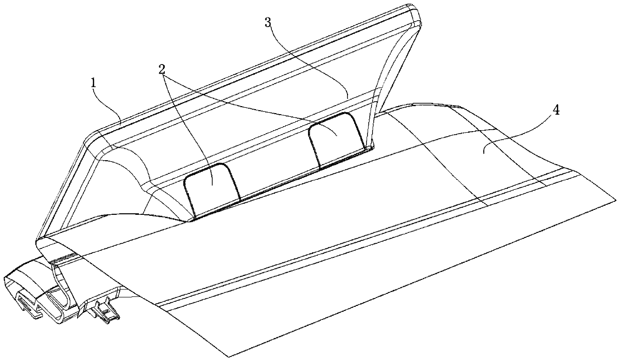
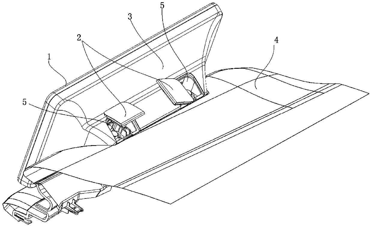
[0002] At present, the suspension screen structure is widely used in the car multimedia display assembly. When the suspension screen is installed on the instrument panel, a part of the display assembly will be exposed. After the rear shell lock screw is fixed, the exposed screw will affect the appearance. The cover used to cover the screws is used as a decoration to solve the problem that the exposed screws affect the appearance. Therefore, when locking the screws, the cover needs to be opened first. The cover and the rear shell are connected by a cantilever rod to prevent the cover from falling off. Install the cover after the screw. The existing cover has two structures. One is the cover with a rectangular cantilever structure. The cover with this structure cannot be rotated after the cover is opened. The cover blocks the line of sight of the locking screw, which is inconvenient. Operation; the other is the cover body with a straight circular cantilever rod structure. The cover body of this structure can be rotated after opening the cover. Because the cantilever rod is straight, it can be rotated at any angle, but the cantilever rod has no fixed angle. direction, the cover body will inevitably turn around, and there will still be a problem that the cover body blocks the sight of the locking screw. In the process of locking the screw, the operator needs to rotate the cover body frequently, which is time-consuming, laborious, inconvenient, and wastes man-hours. , affecting work efficiency

Method used


Image

  • Vehicle-mounted display screen mounting structure
  • Vehicle-mounted display screen mounting structure
  • Vehicle-mounted display screen mounting structure

Examples


Embodiment Construction

[0048] The following will clearly and completely describe the technical solutions in the embodiments of the present invention with reference to the accompanying drawings in the embodiments of the present invention. Obviously, the described embodiments are only some, not all, embodiments of the present invention. Based on the embodiments of the present invention, all other embodiments obtained by persons of ordinary skill in the art without making creative efforts belong to the protection scope of the present invention.

[0049] In the present invention, for a clearer description, the following explanations are made: the terms "inside", "middle", "periphery", "side", "top", "top", "inner wall", "inner" , "bottom" and other indication orientations or positional relationships are based on the orientations or positional relationships set in the drawings, and are only for the convenience of clearly describing the present invention, rather than indicating or implying that the structu...


PUM


Abstract

The invention discloses a vehicle-mounted display screen mounting structure. The vehicle-mounted display screen mounting structure comprises a display screen assembly, a rear shell and a cover body, wherein the display screen assembly is arranged on the rear shell; at least one mounting groove is formed in the rear shell, a positioning hole is formed in the at least one mounting groove, and a chamfer is formed at the top end of the positioning hole; the cover body is provided with a cantilever rod, the cantilever rod is matched with the positioning hole, and the cantilever rod comprises a circuitous part and a guide part; the circuitous part is of an arc-shaped structure, one end of the circuitous part is connected with the cover body, and the other end of the circuitous part is connectedwith the guide part; and a protrusion is arranged at the end, close to the circuitous part, of the guide part. The vehicle-mounted display screen mounting structure solves the technical problem that the sight of a locking screw is blocked when the cover body rotates, the structural design is simple and practical, frequent rotation of the cover body is reduced, time and labor are saved, operation is convenient, and the operation efficiency is improved.

Description

technical field [0001] The invention relates to the field of vehicle-mounted electronic products, in particular to a vehicle-mounted display screen installation structure. Background technique [0002] At present, the suspension screen structure is widely used in the car multimedia display assembly. When the suspension screen is installed on the instrument panel, a part of the display assembly will be exposed. After the rear shell lock screw is fixed, the exposed screw will affect the appearance. The cover used to cover the screws is used as a decoration to solve the problem that the exposed screws affect the appearance. Therefore, when locking the screws, the cover needs to be opened first. The cover and the rear shell are connected by a cantilever rod to prevent the cover from falling off. Install the cover after the screw. The existing cover has two structures. One is the cover with a rectangular cantilever structure. The cover with this structure cannot be rotated after ...

Claims


Application Information

Patent Timeline
Patent Type & Authority Applications(China)
IPC IPC(8): B60R11/02
CPCB60R11/0229B60R2011/0005B60R2011/0007B60R2011/0042
Inventor 杨志明黄位光
Owner FORYOU GENERAL ELECTRONICS
Learn More