A shallow layer carbonization device for carbonized wood
A carbonization device and carbonized wood technology, which is used in household refrigeration devices, charcoal burning/combustion, lighting and heating equipment, etc. Plank distance, etc.
- Summary
- Abstract
- Description
- Claims
- Application Information
AI Technical Summary
Problems solved by technology
Method used
Image
Examples
Embodiment 1
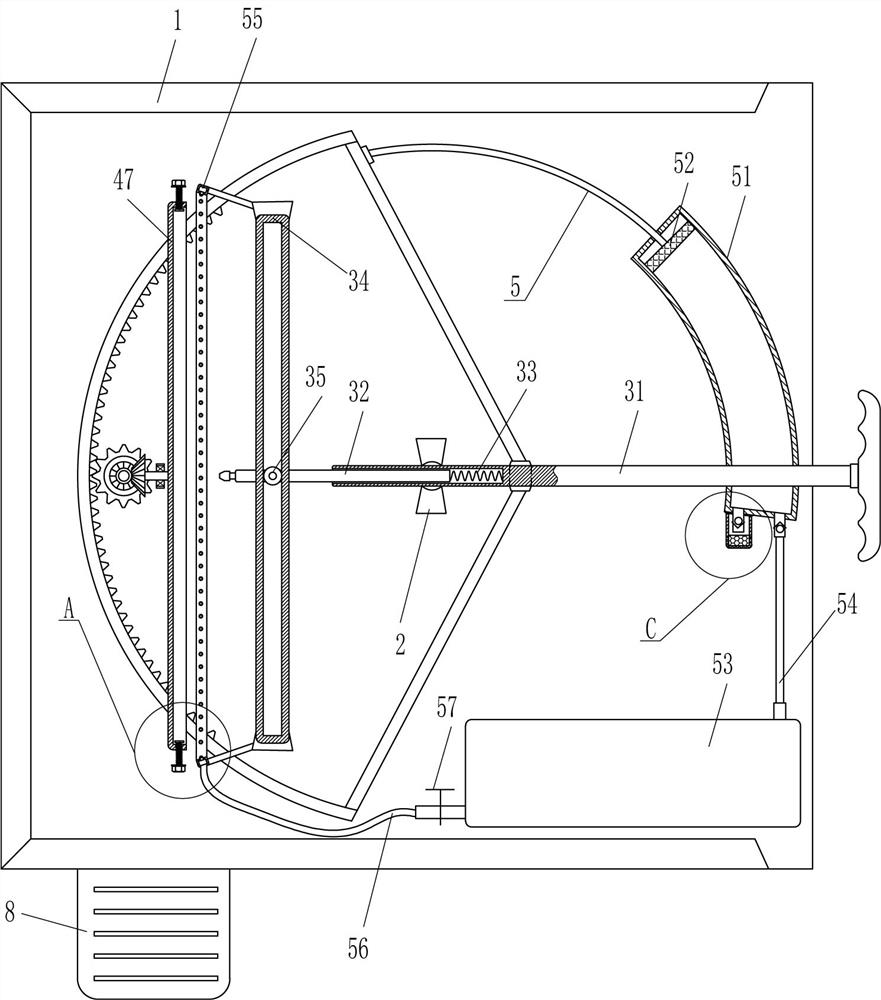
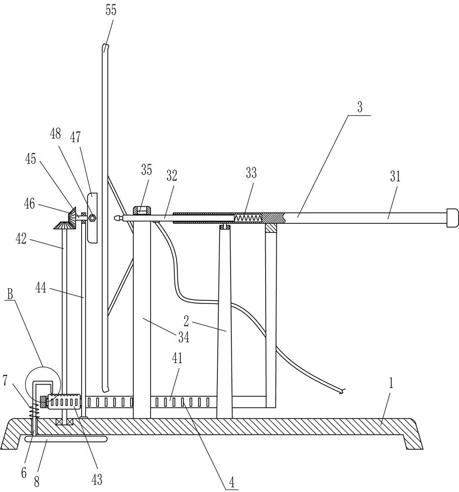
[0022] A shallow layer carbonization device for carbonized wood, such as Figure 1-4 As shown, it includes a base 1, a pole 2, a swing device 3 and a clamping and rotating device 4. The middle of the top of the base 1 is fixedly connected with a pole 2 through a bolt connection, and the top of the pole 2 is provided with a swing device 3. The oscillating device 3 can make the flame carbonize the wood more evenly. The top left side of the base 1 is provided with a clamping and rotating device 4. The clamping and rotating device 4 is used to clamp the wood and can rotate under the drive of the oscillating device 3. .
[0023] Swing device 3 includes hollow swing rod 31, telescopic fire spray pipe 32, first spring 33, N-type guide frame 34 and roller 35, and pole 2 top is provided with hollow swing rod 31 in the mode of rotary type, and this hollow swing Sliding inside the rod 31 is provided with a telescopic fire spray pipe 32, a first spring 33 is connected between the right e...
Embodiment 2
[0027] On the basis of Example 1, such as Figure 1-3 As shown, a cooling device 5 is also included, and the cooling device 5 includes an arc compression cylinder 51, an arc piston rod 52, an air storage cylinder 53, a vent pipe 54, an annular perforated pipe 55, a flexible pipe 56 and a valve 57. The base 1 An arc compression cylinder 51 is installed at the rear right side, and an arc piston rod 52 is slidably provided in the arc compression cylinder 51. The arc piston rod 52 is equipped with a piston and is located in the arc compression cylinder 51. The left end of the piston rod 52 is connected with the curved rack 41, and the front of the right side of the base 1 is provided with an air storage cylinder 53, and an air pipe 54 is sealed between the air storage cylinder 53 and the arc compression cylinder 51. The N-shaped guide frame 34 An annular perforated pipe 55 is arranged on the left side, and the annular perforated pipe 55 is located on the right side of the placemen...
Embodiment 3
[0030] On the basis of Example 2, such as Figure 1-5 As shown, it also includes a special-shaped clamping rod 6, a second spring 7 and a pedal 8. The left side of the base 1 is movable with a special-shaped clamping rod 6, and the top of the column gear 43 is evenly distributed with clamping holes 9 around the top. The upper end of the special-shaped clamping rod 6 is matched, and a second spring 7 is connected between the special-shaped clamping rod 6 and the base 1 . A pedal 8 is installed at the lower end of the special-shaped clamping rod 6 , and the pedal 8 extends out of the base 1 .
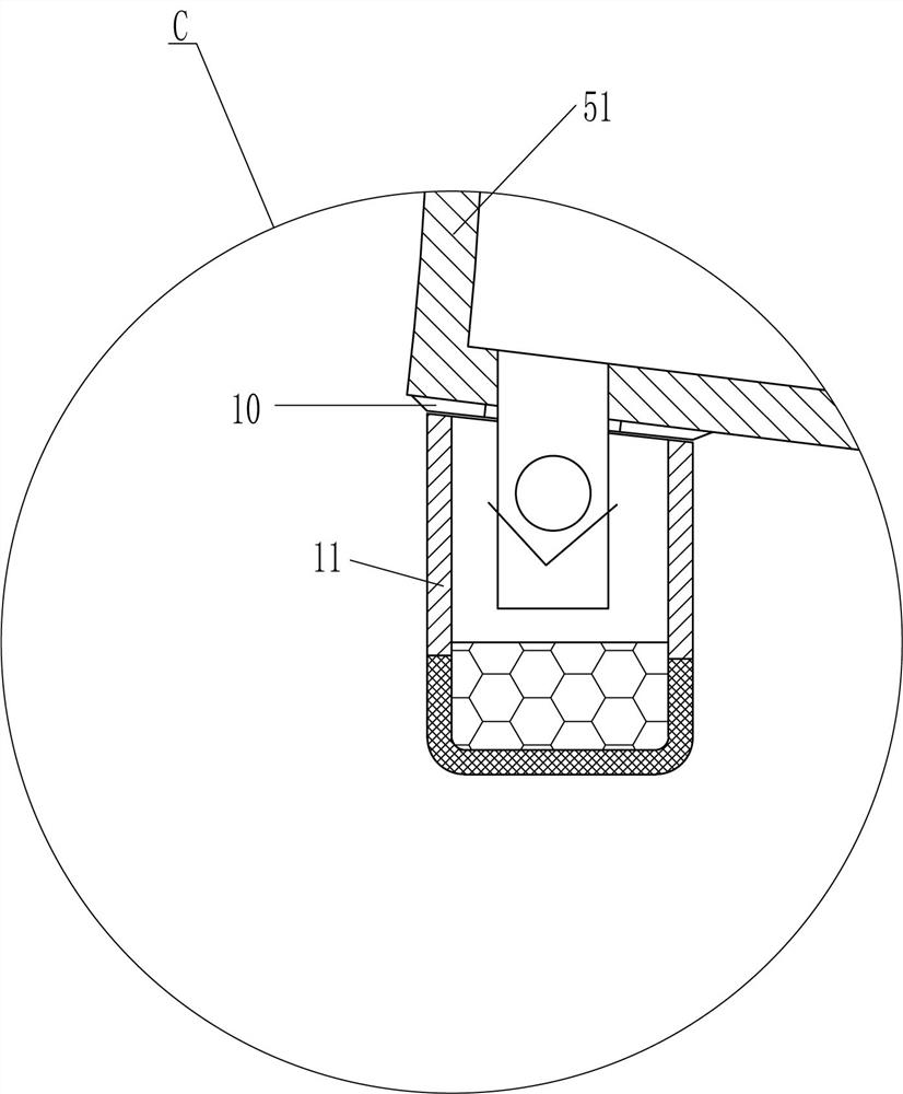
[0031] It also includes a ring magnet 10 and a magnetic filter screen cover 11. The arc-shaped compression cylinder 51 is provided with a ring magnet 10 at the air inlet, and the magnetic filter screen cover 11 is adsorbed on the ring magnet 10 by means of magnetic attraction.
[0032] When the operator assembles or removes the wooden board, the operator can step on the pedal 8, the pedal...
PUM
 Abstract
Description
Claims
Application Information
 - R&D
- Intellectual Property
- Life Sciences
- Materials
- Tech Scout
- Unparalleled Data Quality
- Higher Quality Content
- 60% Fewer Hallucinations
Browse by: Latest US Patents, China's latest patents, Technical Efficacy Thesaurus, Application Domain, Technology Topic, Popular Technical Reports.
© 2025 PatSnap. All rights reserved.Legal|Privacy policy|Modern Slavery Act Transparency Statement|Sitemap|About US| Contact US: help@patsnap.com


