
Metal powder forming device

A metal powder and fan-shaped technology, which is applied in the field of metal powder forming devices, can solve the problems of large ejection force and inability to demold, and achieve the effects of reducing the ejection force, improving safety, and improving integrity

Active Publication Date: 2020-04-10
HARBIN ENG UNIV
View PDF21 Cites 0 Cited by
  • Summary
  • Abstract
  • Description
  • Claims
  • Application Information

AI Technical Summary

Problems solved by technology

When the mold is pressing some special metal powders, such as: nano-aluminum powder, it will generate a lot of heat, which is dangerous
And this kind of pressing method will produce a large ejection force when pressing some long-length blanks, and sometimes even exceed the maximum load of the press, resulting in failure to eject

Method used


Image

  • Metal powder forming device
  • Metal powder forming device

Examples


Embodiment Construction

[0023] The present invention will be further described in detail below in conjunction with the accompanying drawings and specific embodiments.

[0024] The following will clearly and completely describe the technical solutions in the embodiments of the present invention with reference to the accompanying drawings in the embodiments of the present invention. Obviously, the described embodiments are only some, not all, embodiments of the present invention. Based on the embodiments of the present invention, all other embodiments obtained by persons of ordinary skill in the art without making creative efforts belong to the protection scope of the present invention.

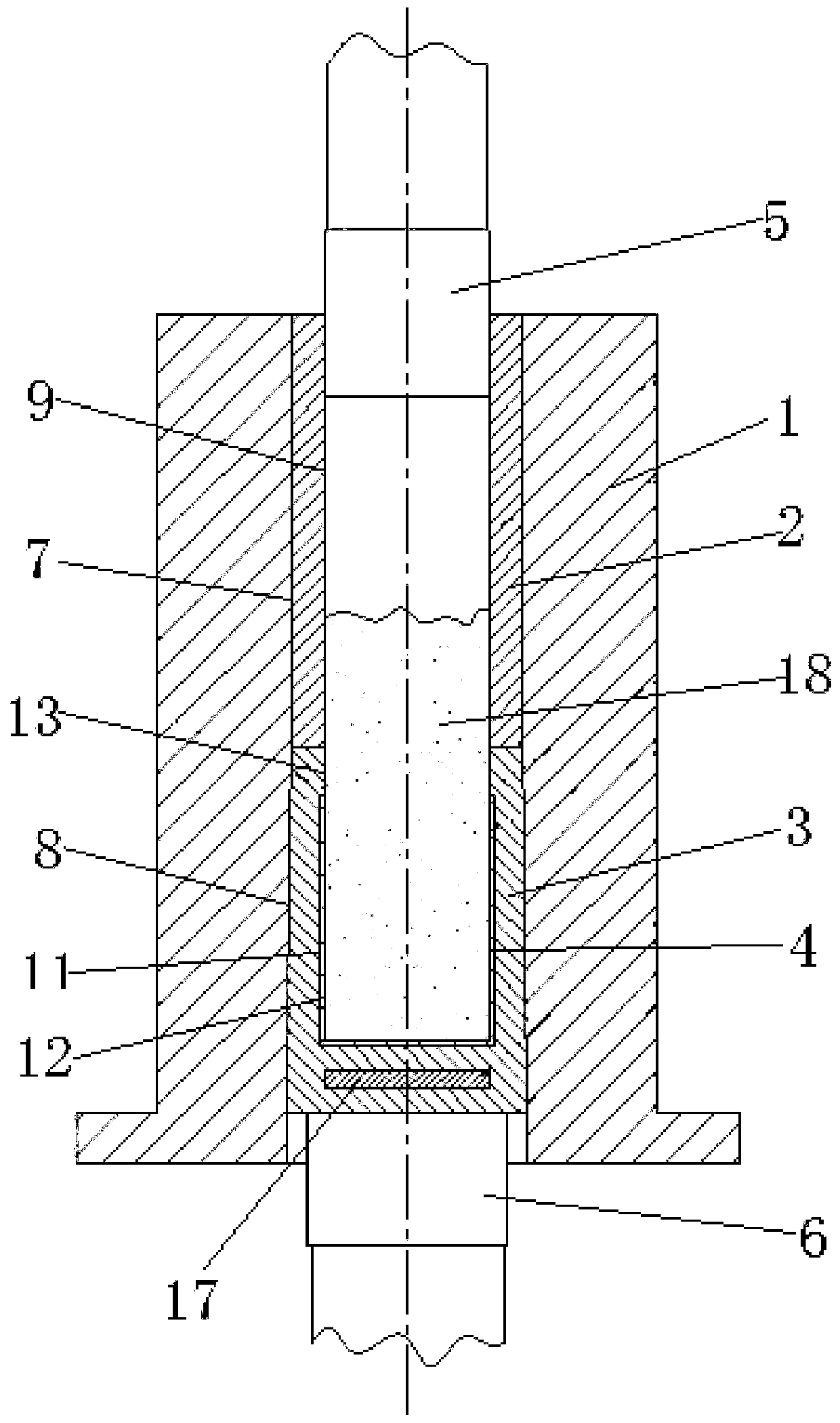
[0025] The purpose of the present invention is to provide a metal powder forming device to solve the problems existing in the prior art, greatly reduce the demoulding force generated during demoulding, and improve the safety of product forming and the integrity of the product.

[0026] In order to make the above objec...


PUM

PropertyMeasurementUnit
angleaaaaaaaaaa

Abstract

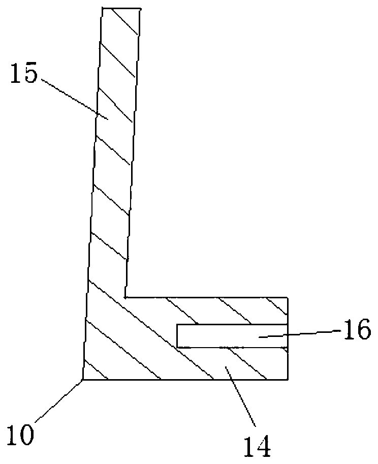
The invention discloses a metal powder forming device, and relates to the technical field of forming devices. The metal powder forming device comprises a mold, an upper sleeve, a lower sleeve, a blankouter shell, an upper punch head and a lower punch head, a cylindrical hole and a conical hole which communicate with each other in an up-down mode are formed in the mold, the upper sleeve is a cylindrical barrel matched with the cylindrical hole, a through hole is formed in the center of the upper sleeve, the lower sleeve is a conical barrel matched with the conical hole, the lower sleeve is formed by a plurality of sleeve parts which are detachably connected, the upper surface of the lower sleeve can be in contact with the lower surface of the upper sleeve, a first cylindrical groove is formed in the center of the upper surface of the lower sleeve, the blank outer shell is a cylindrical shell body matched with the first cylindrical groove, a second cylindrical groove is formed in the center of the blank outer shell, the second cylindrical groove has the same diameter as the through hole, the upper punch head is a cylindrical punch head matched with the through hole and can move up and down, and the lower punch head is used for supporting the lower sleeve and can move up and down. The demoulding force produced during demoulding is lowered, and the safety of product forming and the integrity of products are improved.

Description

technical field [0001] The invention relates to the technical field of forming devices, in particular to a metal powder forming device. Background technique [0002] Powder forming is the process of compacting metal powder into a compact with a certain shape, size, density and strength. It is one of the basic processes of powder metallurgy process. [0003] Before the powder is formed, the metal powder is usually pretreated to meet the requirements of the forming. When mixing materials, generally a certain amount of powder forming additives must be added. [0004] Powder forming is divided into two categories: powder compression forming and powder special forming. [0005] Powder compression forming, also known as powder compression forming, or compaction for short, is the earliest forming method used in powder metallurgy production. At the end of the 18th century and the beginning of the 19th century, Russia and the United Kingdom used steel molds to make platinum produ...

Claims


Application Information

Patent Timeline
Patent Type & Authority Applications(China)
IPC IPC(8): B22F3/03
CPCB22F3/03
Inventor 刘平安刘晗聪宋乃孟丁涛王璐
Owner HARBIN ENG UNIV
Learn More