High-speed wet mixing granulator

A high-speed wet method and granulator technology, applied in mixers, mixers with rotary stirring devices, chemical instruments and methods, etc., can solve the problems of prolonging the mixing time of materials, low linear speed, reducing efficiency, etc. Mixing effect, increase work efficiency, increase the effect of mixing speed

Inactive Publication Date: 2020-04-10
马意元
View PDF2 Cites 1 Cited by
  • Summary
  • Abstract
  • Description
  • Claims
  • Application Information

AI Technical Summary

Problems solved by technology

[0003] Since the existing stirring paddle is only a simple paddle, it can only pick up the material at this place and exert a forward force during the stirring process, and only a small amount of material on the upper part can use the upper half of the cylinder wall. The partial conical structure makes it move radially and fall into the center for secondary mixing. Most of the remaining materials are still mixed near the original movement circle, and the materials near the center of the stirring shaft are mixed due to the small internal linear velocity. The effect is not guaranteed, and in the mixed material, only the material on the circumference of the cutting knife can be cut after a period of mixing and cutting to complete the cutting of the material with large particles on the circumference, while the other parts of the material are more difficult to cut , which reduces the mixing effect of the material, and also prolongs the mixing time of the material, reducing the efficiency

Method used


Image

  • High-speed wet mixing granulator
  • High-speed wet mixing granulator
  • High-speed wet mixing granulator

Examples


Embodiment Construction

[0018] The following will clearly and completely describe the technical solutions in the embodiments of the present invention with reference to the accompanying drawings in the embodiments of the present invention. Obviously, the described embodiments are only some, not all, embodiments of the present invention. Based on the embodiments of the present invention, all other embodiments obtained by persons of ordinary skill in the art without making creative efforts belong to the protection scope of the present invention.

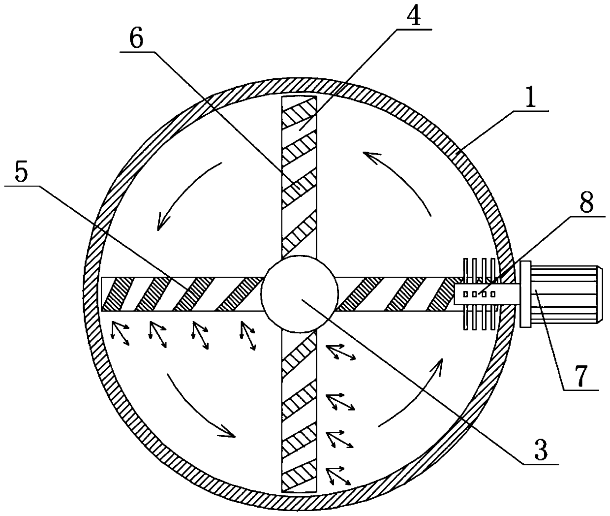
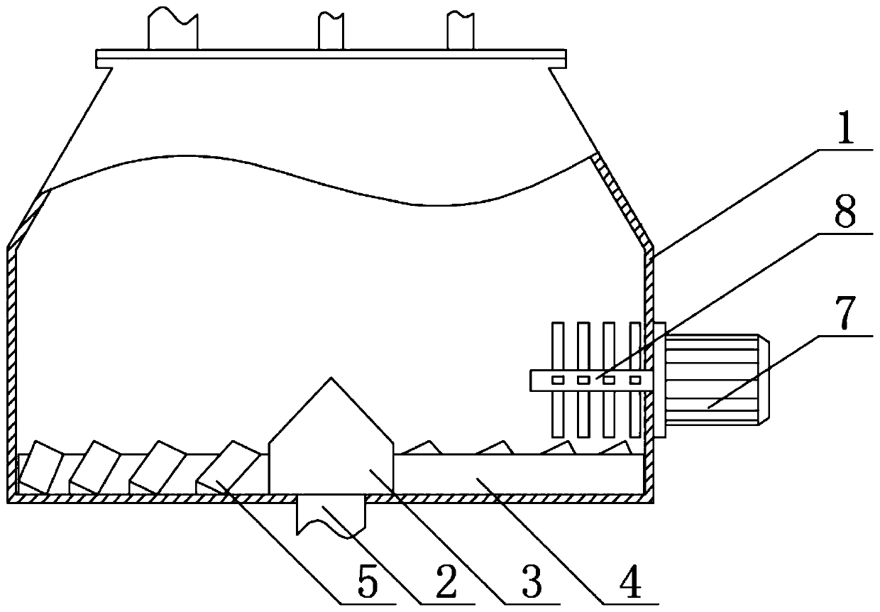
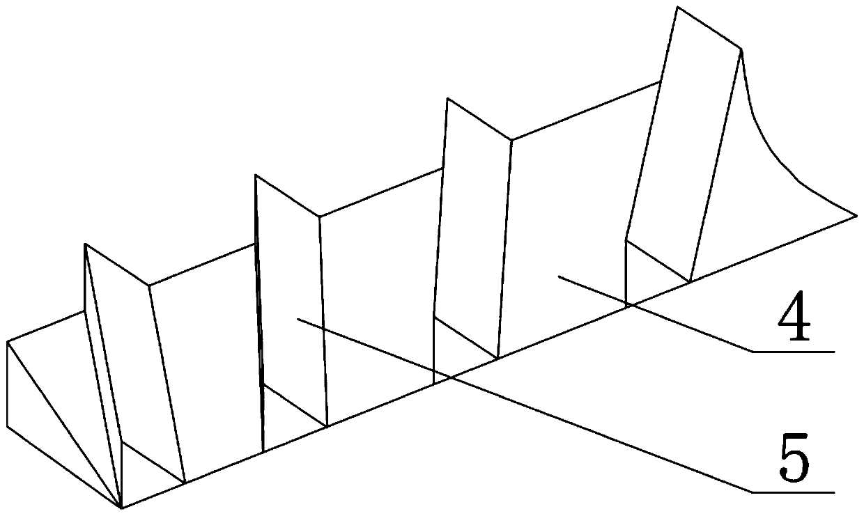
[0019] see Figure 1-4 , a high-speed wet mixing granulator, including a body 1, the center of the bottom of the body 1 is movably connected with a transmission shaft 2, the upper part of the transmission shaft 2 is fixedly connected with a center cone 3, and the outer wall of the center cone 3 is fixedly equipped with a stirring blade 4 , the first direction blade 5 is installed on the horizontal surface of the stirring blade 4, the second direction blade 6 i...


PUM


Abstract

The invention relates to the technical field of mixing equipment, and discloses a high-speed wet mixing granulator, which includes a machine body. In the high-speed wet mixing granulator, first-direction blades or second-direction blades the angle between which and the length direction of stirring blades increases gradually from inside to outside are arranged at intervals on the upper surfaces ofthe four stirring blades. A characteristic that a direction blade close to the center has a small angle with the length of the stirring blades, but has long length, can be utilized so that the linearvelocity of the part, of the stirring blades, close to the center rotating shaft is far smaller than the linear velocity of parts close to the inner wall, and the local material mixing speed can be increased under lifting functions at a direction where the center angle is small, the material uplifting direction of the direction blades is different from the material uplifting direction of the stirring blades so that random motion mixing of center materials can be achieved, and two adjacent direction blades have opposite directions so that the mixing effect of the center materials can be improved, thus improving the mixing effect of overall materials.

Description

technical field [0001] The invention relates to the technical field of mixing equipment, in particular to a high-speed wet mixing granulator. Background technique [0002] The stirring paddle of the existing high-speed mixing granulator is composed of three stirring blades, and the stirring blade has a folded edge near the edge of the cylinder wall, and the bottom surface of the stirring blade is close to the bottom of the cylinder, and the stirring blade is driven to rotate by the transmission mechanism at the bottom. , use the inclined surface of the stirring paddle to pick up and stir the material, so that the material is rotated and mixed, combined with the cutting knife on the side, the mixed material is cut into particles, but the existing high-speed mixing granulator always has the following problems: [0003] Since the existing stirring paddle is only a simple paddle, it can only pick up the material at this place and exert a forward force during the stirring process...

Claims


Application Information

Patent Timeline
Patent Type & Authority Applications(China)
IPC IPC(8): B01F7/18B01F13/10B01J2/10
CPCB01J2/10B01F27/11B01F27/90B01F33/80B01F33/83611
Inventor 马意元
Owner 马意元
Why Eureka
Try Eureka