
Bioscience soil sampling detection device

A soil sampling and testing device technology, applied to the sampling device and other directions, can solve the problems of inability to sample soil and inconvenient use, and achieve the effects of accurate soil detection, convenient operation and simple operation.

Inactive Publication Date: 2020-04-07
HUBEI UNIV
View PDF1 Cites 11 Cited by
  • Summary
  • Abstract
  • Description
  • Claims
  • Application Information

AI Technical Summary

Problems solved by technology

[0005] Based on the technical problem that the existing soil sampling device cannot sample soil at different depths at the same time and is inconvenient to use, the present invention proposes a biological science soil sampling detection device

Method used


Image

  • Bioscience soil sampling detection device
  • Bioscience soil sampling detection device
  • Bioscience soil sampling detection device

Examples


Embodiment 1

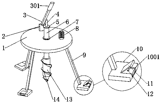
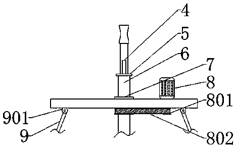
[0030] refer to Figure 1-6 , a biological science soil sampling detection device, comprising a plate body 1 and a first sliding rod 6, the top middle of the plate body 1 is provided with a first through hole, and the plate body 1 is provided with a fixed hole at the first through hole. Ring 7, the middle part of the fixed ring 7 is provided with a circular through hole, the first sliding rod 6 is slidably connected with the fixed ring 7 at the circular through hole, and the side of the plate body 1 is provided with a second through hole. hole, the plate body 1 is fixedly installed with a motor 8 at the second through hole, the bottom end of the first sliding rod 6 is rotatably connected with a drum 13, and the inside of the drum 13 is provided with three sliding boxes 18, The bottom end of the rotating cylinder 13 is threadedly connected with a drill bit 20, and the outer parts of the rotating cylinder 13 and the drilling bit 20 are welded with a spiral piece 14, and the rota...

Embodiment 2

[0039] refer to Figure 7 , a bioscience soil sampling detection device. Compared with Embodiment 1, in this embodiment, in order to be able to measure the depth of soil sampling of the device, the top of the plate body 1 is welded with a second rotating shaft 28, and the second rotating shaft 28 A third rotating plate 29 is welded to the top of the third rotating plate 29, and a scale 30 is provided on one side of the third rotating plate 29. By rotating the third rotating plate 29, it can be perpendicular to the plate body 1, so that the first The descending height of the sliding rod 6 can know the sampling depth of the sampling device, which is more conducive to detecting the soil.

[0040] During use, by turning the support rod 9 to make it open, the anti-skid plate 10 can be placed in contact with the ground to make the device stable, and by rotating the second rotating plate 11, the fixed rod 12 can be driven to rotate, and the fixed rod 12 passes through the anti-skid p...


PUM


Abstract

The invention belongs to the technical field of soil sampling, in particular to a bioscience soil sampling detection device. Since existing soil sampling devices cannot sample soil of different depthsat the same time, the use is inconvenient. Presented are solutions, the device comprises a plate body and a first sliding rod, a first through hole is formed in the middle of the top end of the platebody; a fixing ring is arranged at the first through hole of the plate body; a circular through hole is formed in the middle of the fixing ring, the first sliding rod is slidably connected with the fixing ring at the circular through hole, a second through hole is formed in one side of the plate body, a motor is fixedly installed at the second through hole of the plate body, a rotating cylinder is rotatably connected to the bottom end of the first sliding rod, and three sliding boxes are arranged in the rotating cylinder. The rotary drum is driven by the motor to rotate into soil, soil of different depths can enter the sampling box through sliding of the sliding box, and therefore soil of different depths can be sampled at the same time, and data are more accurate during soil detection.

Description

technical field [0001] The invention relates to the technical field of soil sampling, in particular to a bioscience soil sampling detection device. Background technique [0002] At present, my country's soil environment is grim. The overall situation of soil pollution in my country is not optimistic. Some areas have serious soil pollution. The quality and safety of agricultural products and mass incidents caused by soil pollution are increasing year by year, becoming an important factor affecting the health of the masses and social stability. [0003] For biological science research, soil planting is often used. In order to investigate the soil environment, soil sampling and detection is an indispensable step in the prevention and control of soil pollution. Soil sampling usually needs to detect soil at different depths. Traditional manual soil sampling often takes a long time Excavating the land, on the one hand, increases the labor intensity of the staff, on the other hand,...

Claims


Application Information

Patent Timeline
Patent Type & Authority Applications(China)
IPC IPC(8): G01N1/08
CPCG01N1/08
Inventor 陈奕帆艾钧钧
Owner HUBEI UNIV
Learn More