
Temperature detection fixer for high-voltage power cable intermediate interface

An intermediate interface and high-voltage power technology, which is applied in the field of high-voltage cables, can solve the problems of cable burnout, interface fracture, and interface weight increase, and achieve the effects of avoiding fracture damage, avoiding impact, and avoiding falling off

Active Publication Date: 2020-04-07
广东电网有限责任公司汕尾供电局
View PDF6 Cites 4 Cited by
  • Summary
  • Abstract
  • Description
  • Claims
  • Application Information

AI Technical Summary

Problems solved by technology

[0002] In the long-distance erection of high-voltage power cables, it is often necessary to carry out temperature detection and real-time monitoring on the intermediate interface of the cable, so as to avoid the high temperature of the intermediate interface due to joint problems when the cable transmits power and burn out the cable. When the temperature is detected, the detector needs to be fixed and attached to the cable. At present, on the outer wall of the middle interface, the detector is directly tied to the cable interface by straps and other tools. The fixing effect of the detector is not good, and it is easy to fall off, and the cable interface itself needs better tensile properties to avoid The interface is broken, and the addition of the detector will easily lead to an increase in the weight of the interface, thereby increasing the pulling force at the interface. The pulling force at the cable interface cannot be reduced by fixing with straps, which will easily lead to problems such as breakage at the interface. Therefore, we propose a temperature detection fixture for the intermediate interface of high-voltage power cables to solve the above problems

Method used


Image

  • Temperature detection fixer for high-voltage power cable intermediate interface
  • Temperature detection fixer for high-voltage power cable intermediate interface
  • Temperature detection fixer for high-voltage power cable intermediate interface

Examples


Embodiment Construction

[0017] The following will clearly and completely describe the technical solutions in the embodiments of the present invention with reference to the accompanying drawings in the embodiments of the present invention. Obviously, the described embodiments are only some, not all, embodiments of the present invention. Based on the embodiments of the present invention, all other embodiments obtained by persons of ordinary skill in the art without making creative efforts belong to the protection scope of the present invention.

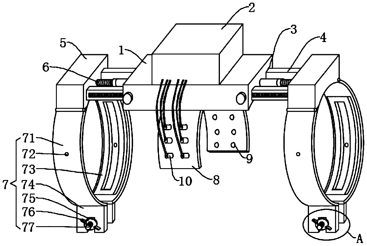
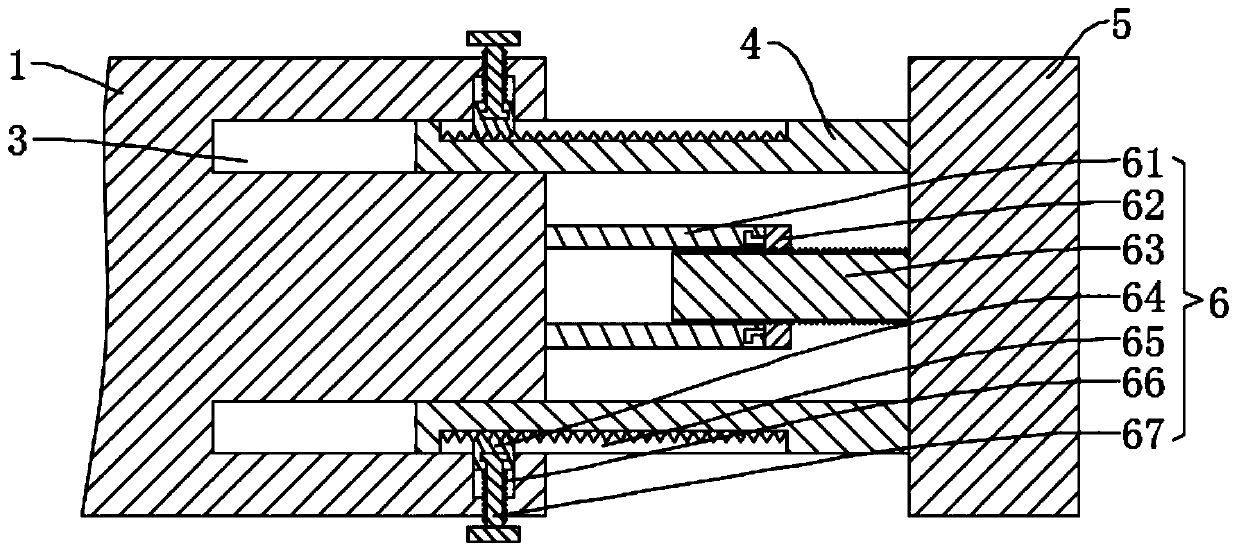
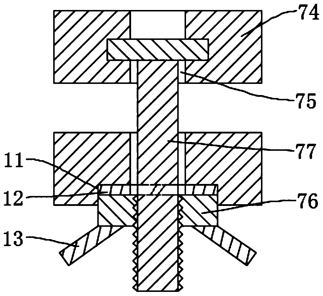
[0018] see Figure 1-5 , the present invention provides a technical solution: a temperature detection fixture for the intermediate interface of a high-voltage power cable, including a mounting plate 1, a detector 2 is fixedly installed on the mounting plate 1, and an arc-shaped pressure gauge is fixedly installed on the bottom of the outer wall on both sides of the mounting plate 1. There are multiple mounting holes 9 on the sheet 8 and the arc-shaped pressing...


PUM


Abstract

The invention discloses a temperature detection fixer for a high-voltage power cable intermediate interface, which comprises a mounting plate, a detector is mounted on the mounting plate, sliding grooves are formed in the end surfaces of the two ends of the mounting plate, one end of a supporting plate is slidably clamped in each sliding groove, the other end of the supporting plate is fixedly connected with a connecting plate, and a tensioning mechanism is mounted between the end surfaces of the connecting plate and the mounting plate. The mounting plate clings to the cable interface; the arc-shaped pressing sheet clings to the outer wall of the interface; the supporting plate slides along the sliding groove. Therefore, the connecting plate is moved to cables at two ends of the interface.The connecting plate is quickly clamped and fixed on cables at two ends of the interface through the clamping sleeve; the mounting plate is fixed firmly, the detector is avoided from falling off, theconnecting plate is pulled through the tensioning mechanism, so that the connecting plate slightly moves towards the mounting plate, the weight of the mounting plate is transmitted to cables at the two ends of the interface through the connecting plate, the middle interface below the mounting plate is in a loose state, the middle interface is prevented from being broken and damaged due to pulling, and the detector can conveniently detect the temperature of the middle interface.

Description

technical field [0001] The invention relates to the technical field of high-voltage cables, in particular to a temperature detection fixer for an intermediate interface of a high-voltage power cable. Background technique [0002] In the long-distance erection of high-voltage power cables, it is often necessary to carry out temperature detection and real-time monitoring on the intermediate interface of the cable, so as to avoid the high temperature of the intermediate interface due to joint problems when the cable transmits power and burn out the cable. When the temperature is detected, the detector needs to be fixed and attached to the cable. At present, on the outer wall of the middle interface, the detector is directly tied to the cable interface by straps and other tools. The fixing effect of the detector is not good, and it is easy to fall off, and the cable interface itself needs better tensile properties to avoid The interface is broken, and the addition of the detecto...

Claims


Application Information

Patent Timeline
IPC IPC(8): G01K1/14
CPCG01K1/14
Inventor 李聪
Owner 广东电网有限责任公司汕尾供电局
Learn More