Automobile side wall frame reinforcing assembly

A technology for strengthening components and car sides, applied to vehicle components, upper structure, upper structure sub-assembly, etc., can solve problems such as weak lap joints between B-pillar and door sill, large deformation, and discontinuous strength

Pending Publication Date: 2020-04-07
SAIC-GM-WULING AUTOMOBILE CO LTD
View PDF0 Cites 3 Cited by
  • Summary
  • Abstract
  • Description
  • Claims
  • Application Information

AI Technical Summary

Problems solved by technology

In the face of higher safety performance requirements, the traditional body structure is difficult to meet the requirements, the main problems are as follows:
[0005] 1) The collision energy increases, the collision joint point moves upward, and the improper design of the strength of the B-pillar leads to unreasonable deformation and large intrusion;
[0006] 2) The layout of the sill partition 2 is unreasonable, and there is no partition on the outer side of the rear floor crossbeam corresponding to it, resulting in fewer force transmission paths and lower force transmission efficiency in side collisions;
[0008] 4) "Integral" or "split in the same direction" sill partition 2 is insufficient to strengthen the sill, the force transmission efficiency is low, and the sill turns seriously;
[0009] 5) The lap joint between the B-pillar and the sill is weak, resulting in insufficient dispersion of force transmission, large force on the upper end of the B-pillar, large deformation, and high intrusion speed;
[0010] 6) The overlap between the front floor beam and the sill cavity is small, the overlapping structure is weak, and the support is insufficient, which leads to serious overturning of the sill and a large amount of intrusion during a collision
[0011] 7) The local reinforcement plate of the side frame of the body is interrupted, the joint is weak, the strength is discontinuous, it is easy to tear and fail under extreme collision conditions, and the intrusion is large

Method used


Image

  • Automobile side wall frame reinforcing assembly
  • Automobile side wall frame reinforcing assembly
  • Automobile side wall frame reinforcing assembly

Examples


Embodiment Construction

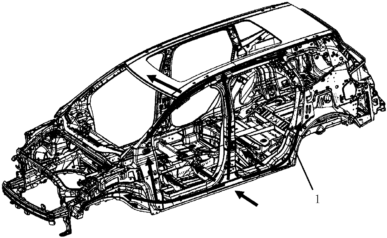
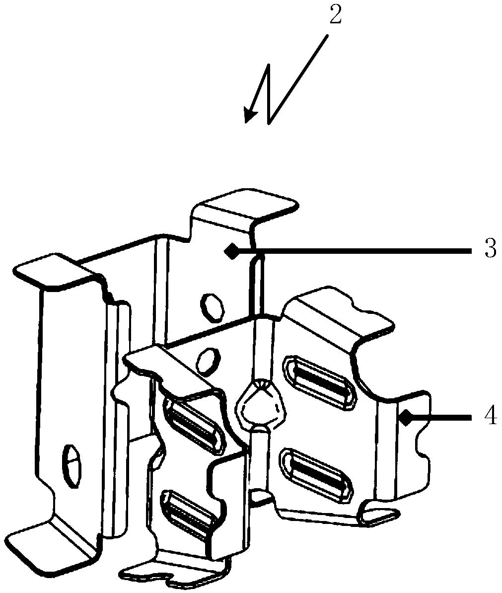
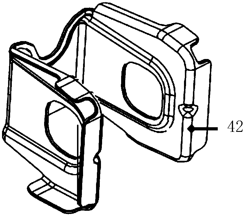
[0046] The following with attached Figure 4 to Figure 14 A further detailed description will be given to a reinforcement component of the automobile side wall frame of the present invention.

[0047] A kind of automobile side frame reinforcement assembly of the present invention, please refer to Figure 4-14 , including an A-pillar reinforcement assembly, a B-pillar reinforcement assembly 11, a door sill reinforcement assembly, a C-pillar reinforcement assembly 21, a D-pillar reinforcement assembly, a side wall upper side sill reinforcement assembly 12 and a rear side wall connection assembly, the upper part of the A-pillar reinforcement assembly The inner side is fixed on the outer side of the upper end of the front body frame, the inner side of the middle and lower part of the A-pillar reinforcement assembly is fixed on the side of the floor, and the upper rear end of the A-pillar reinforcement is fixed on the front end of the side sill reinforcement assembly , the lower r...


PUM


Abstract

The invention discloses an automobile side wall frame reinforcing assembly, which comprises an A-pillar reinforcing assembly, a B-pillar reinforcing assembly, a threshold reinforcing assembly, a C-pillar reinforcing assembly, a D-pillar reinforcing assembly, a side wall roof side rail reinforcing assembly and a rear side wall connecting assembly. The rear end of the upper part of the A-pillar reinforcing assembly is fixed at the front end of the side wall roof side rail reinforcing assembly. The rear end of the lower part of the A-pillar reinforcing assembly is fixed to the front end of the threshold reinforcing assembly. The upper end part of the B-pillar reinforcing assembly is fixed on the A-pillar reinforcing assembly. The lower end of the B-pillar reinforcing assembly is fixed to thethreshold reinforcing assembly. The rear end of the threshold reinforcing assembly is fixed to the front end of the rear side wall connecting assembly. The upper end of the C-pillar reinforcing assembly is fixed to the side wall roof side rail reinforcing assembly. The upper end of the D-pillar reinforcing assembly is fixed to the rear end of the side wall roof side rail reinforcing assembly. According to the automobile side wall frame reinforcing assembly, the energy absorption capacity of an automobile body structure in the side collision process can be increased, the invasion amount and theinvasion speed are reduced, and threshold overturning is reduced.

Description

technical field [0001] The invention relates to the technical field of automobile frame, in particular to an automobile side frame reinforcement assembly. Background technique [0002] Such as Figure 1-3 As shown, at present, the common load-bearing body generally absorbs, transmits and disperses the side impact force through the B-pillar and the sill, and strengthens the sill by setting a partition in the sill, and transmits the force to the beam structure, and at the same time weakens the The lower end of the B-pillar guides deformation and absorbs energy to protect passengers. [0003] Among them, the design and arrangement of the door sill partitions are different, there are mainly "split in the same direction" design, and "integrated" design; There will be a slight misalignment, and there is no partition design on the crossbeam of the rear frame, and the force is transmitted through the strength of the threshold itself. [0004] With the growth of the market share of...

Claims


Application Information

Patent Timeline
Patent Type & Authority Applications(China)
IPC IPC(8): B62D25/02B62D25/04B62D25/20
CPCB62D25/02B62D25/04B62D25/20
Inventor 劳兵周士智贾丽刚钟巧波汪德强
Owner SAIC-GM-WULING AUTOMOBILE CO LTD
Why Eureka
Try Eureka