Communication equipment mounting device

A technology for communication equipment and installation devices, which is applied in the direction of metal processing equipment, metal processing, manufacturing tools, etc., can solve the problems of inconvenient installation work, troublesome fixed installation, insufficient and weak fixing, etc., and achieve the effect of convenient use and easy installation

Inactive Publication Date: 2020-04-07
JILIN TEACHERS INST OF ENG & TECH
View PDF8 Cites 1 Cited by
  • Summary
  • Abstract
  • Description
  • Claims
  • Application Information

AI Technical Summary

Problems solved by technology

[0003] The fixed installation of communication equipment in the prior art is troublesome, the fixation is not strong enough, the installation work is inconvenient, and the work efficiency is low; therefore, it is necessary to design a communication equipment installation device to solve the above problems

Method used


Image

  • Communication equipment mounting device
  • Communication equipment mounting device
  • Communication equipment mounting device

Examples


Embodiment 1

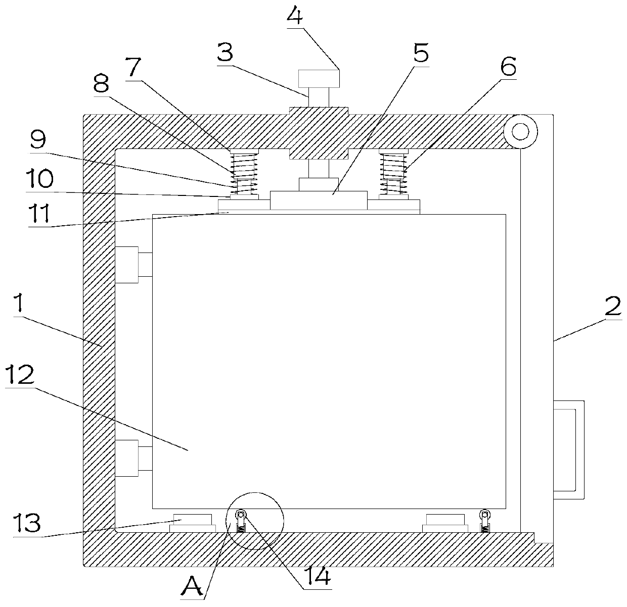
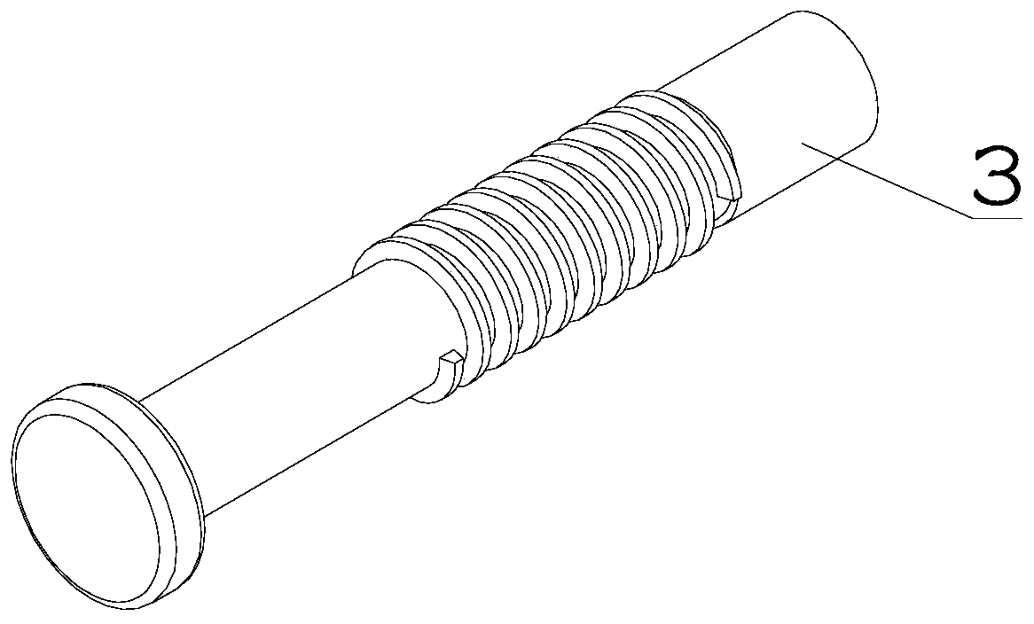
[0020] see Figure 1~3 , in Embodiment 1 of the present invention, a communication equipment installation device includes a main body 1, a communication equipment body 12 is arranged inside the main body 1, and the bottom of the communication equipment body 12 is in contact with an elastic pulley assembly. The communication device body 12 enters the main body 1 to reduce the resistance when entering the main body 1; the main body 1 is also provided with a locking assembly, which includes a driving rod 3, a driving handle 4, a connecting seat 5 and an elastic connecting assembly 6. The outside of the drive rod 3 is provided with a screw thread that matches the threaded hole on the main body 1, the bottom of the drive rod 3 is rotatably connected to the connecting seat 5, the upper end of the drive rod 3 is provided with a drive handle 4, and the drive handle is set 4. It is convenient to drive the driving rod 3 to rotate and adjust the height of the driving rod 3; elastic conne...

Embodiment 2

[0022] see Figure 1~3 The main difference between this embodiment 2 and embodiment 1 is that the elastic connection assembly 6 includes an upper connection seat 7, a telescopic rod 8, an A elastic member 9 and a lower connection seat 10, and the upper connection seat 7 is fixedly installed on the main body 1 Above, the lower connecting seat 10 is fixedly installed on the connecting seat 5, the upper and lower ends of the telescopic rod 8 and the A elastic member 9 are fixedly installed on the upper connecting seat 7 and the lower connecting seat 10 respectively, and the A elastic member 9 are sleeved on the outside of telescopic rod 8.

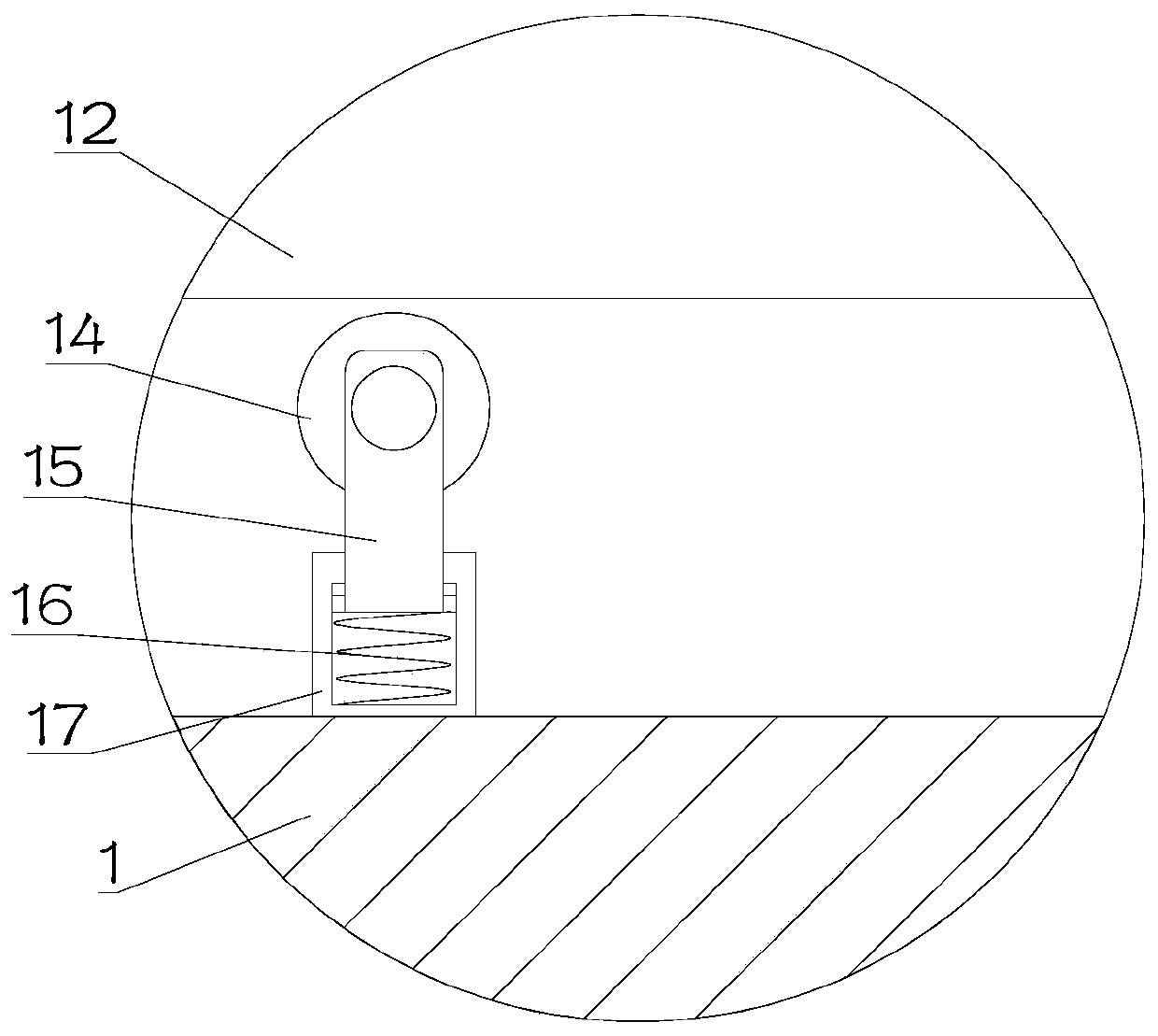
[0023] The pulley assembly includes a roller 14 that is in contact with the communication device body 12. The roller 14 is rotatably mounted on the upper end of the pole 15, and the bottom of the pole 15 slides up and down and is installed in the cavity inside the fixed seat 17. The fixed The seat 17 is fixedly installed on the main body 1, ...


PUM


Abstract

The invention discloses a communication equipment mounting device, and relates to the technical field of communication equipment. The mounting device comprises a main body, a communication equipment body is arranged in the main body, and the bottom of the communication equipment body abuts against an elastically-arranged pulley assembly; a locking assembly is further arranged on the main body; thelocking assembly comprises a driving rod, a driving handle, a connecting seat and an elastic connecting assembly; a thread matched with a threaded hole in the main body is arranged in the outer sideof the driving rod, the bottom of the driving rod is rotatably connected to the connecting base, and the driving handle is arranged at the upper end of the driving rod; elastic connecting assemblies are arranged at the two sides of the connecting base, and the upper ends and the lower ends of the elastic connecting assemblies are fixedly installed on the main body and the connecting base correspondingly. The bottom of the connecting base abuts against the communication equipment body, a rotating cover is further arranged on the main body, and one end of the rotating cover is hinged to the mainbody. The communication equipment body is convenient to install, and the use is convenient.

Description

technical field [0001] The invention relates to the technical field of communication equipment, in particular to a communication equipment installation device. Background technique [0002] The English abbreviation is ICD, and the full name is IndustrialCommunicationDevice. Wireless communication devices are mainly wireless APs, wireless bridges, wireless network cards, wireless lightning arresters, antennas and other equipment. Wireless communication uses radio waves instead of cables to achieve communication between devices. This communication method has Quick and easy installation and maintenance, not affected by the site terrain environment, low cost and other advantages, rich products can meet the different needs of users in terms of communication distance and communication speed. [0003] The fixed installation of the communication equipment in the prior art is cumbersome, the fixing is not strong enough, the installation work is inconvenient, and the work efficiency i...

Claims


Application Information

Patent Timeline
Patent Type & Authority Applications(China)
IPC IPC(8): B23P19/02
CPCB23P19/02
Inventor 吉李满张雪刘强
Owner JILIN TEACHERS INST OF ENG & TECH
Why Eureka
Try Eureka