Pump body assembly and slide vane compressor with same

A pump body and component technology, applied in the field of compressors, can solve the problems affecting the operation performance of pump body components and large suction resistance, so as to improve the operation performance and reduce the initial suction resistance.

Pending Publication Date: 2020-04-03
GREE ELECTRIC APPLIANCES INC
View PDF1 Cites 0 Cited by
  • Summary
  • Abstract
  • Description
  • Claims
  • Application Information

AI Technical Summary

Problems solved by technology

[0004] The main purpose of the present invention is to provide a pump body assembly and a sliding vane compressor with it, so as to solve the problem in the prior art that the performance of the pump body assembly is affected due to the large suction resistance of the pump body assembly

Method used


Image

  • Pump body assembly and slide vane compressor with same
  • Pump body assembly and slide vane compressor with same
  • Pump body assembly and slide vane compressor with same

Examples


Embodiment 1

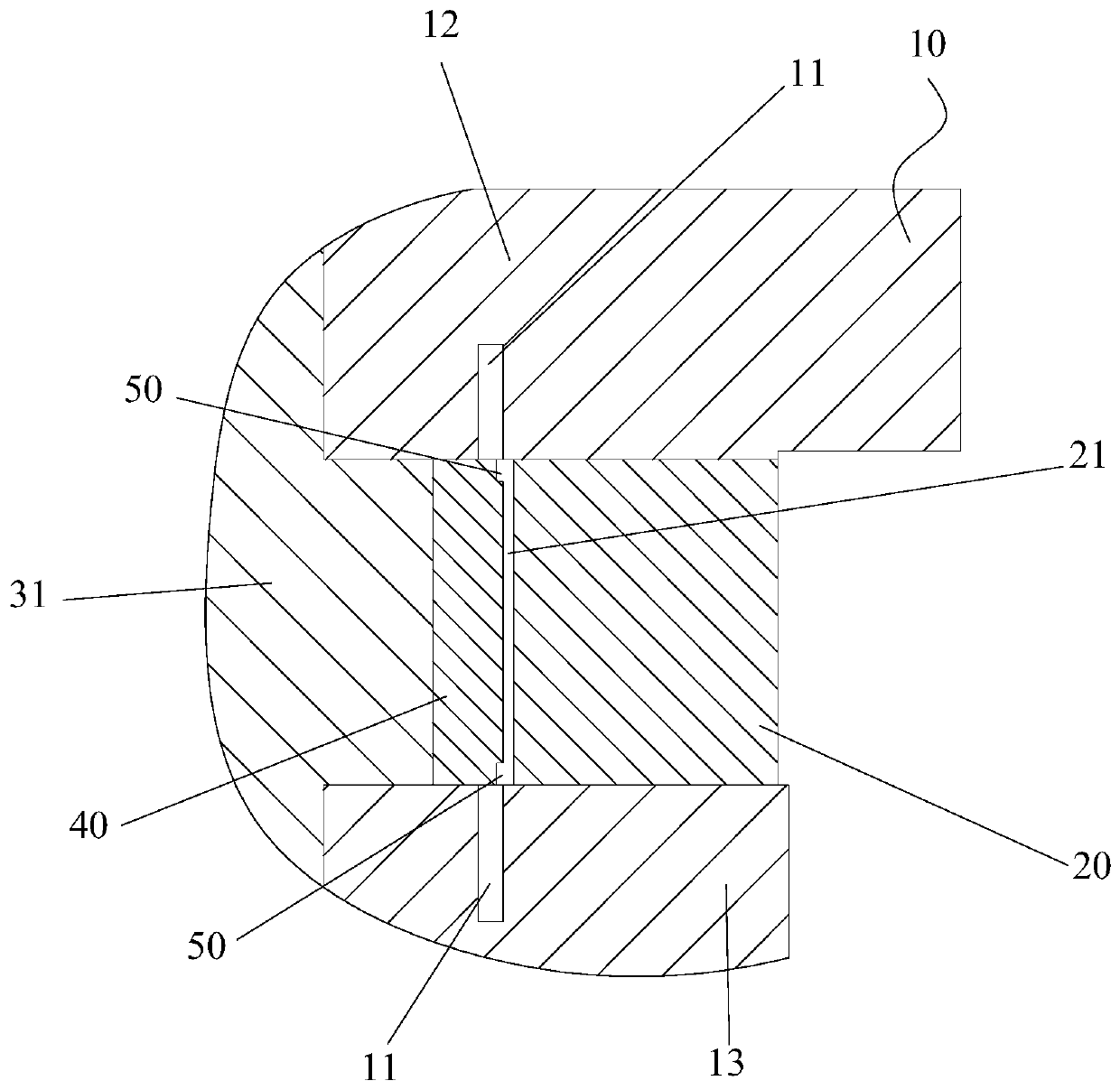
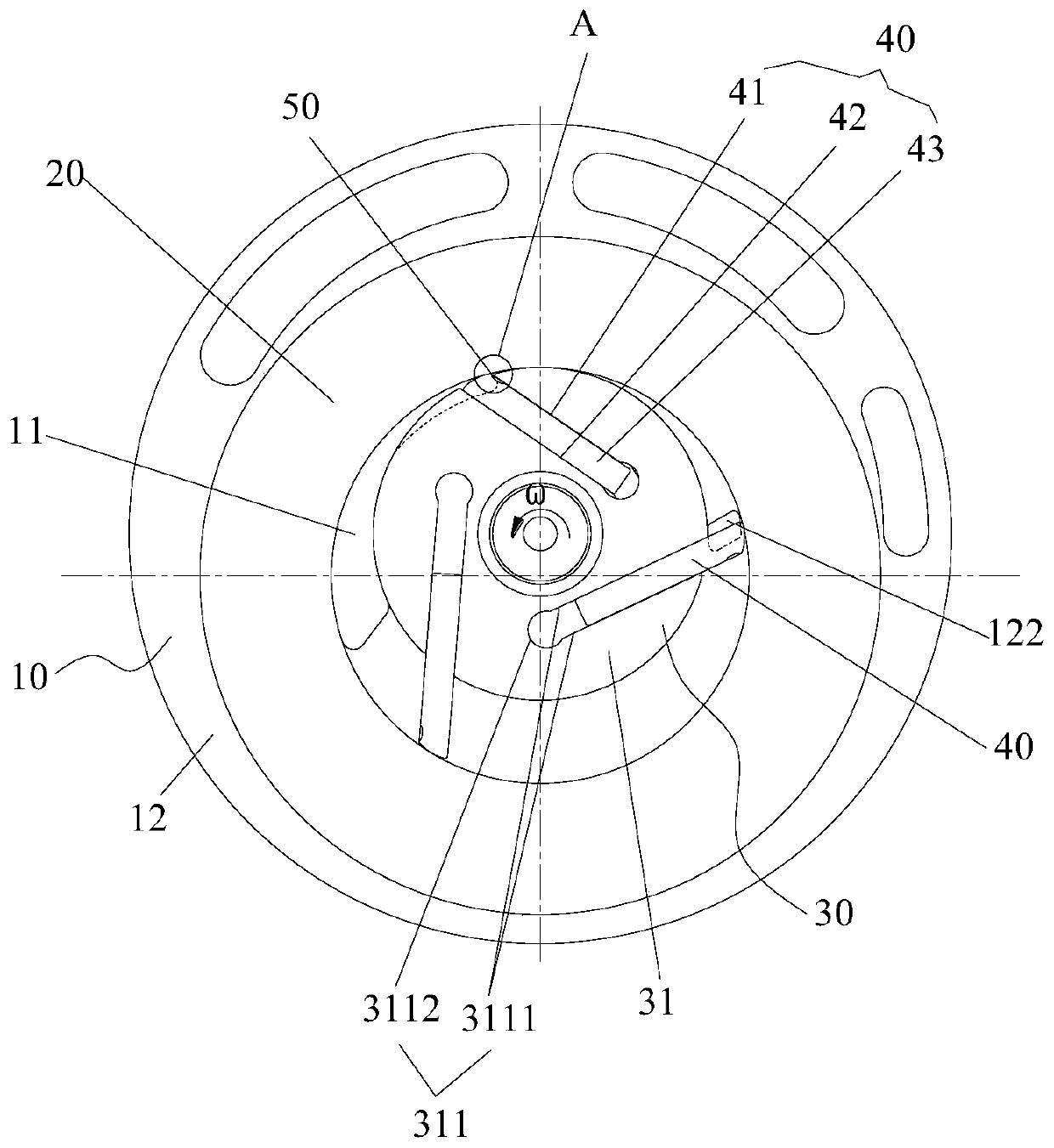
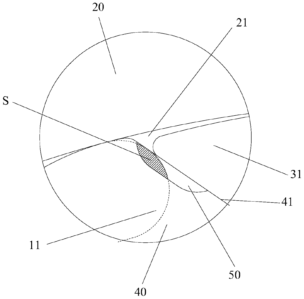
[0038] Such as Figure 1 to Figure 7 As shown, the pump body assembly includes a flange 10, a cylinder 20, a rotating shaft 30 and a plurality of sliding vanes 40, the rotor part 31 of the rotating shaft 30 has a sliding vane groove 311, and the sliding vanes 40 are slidably arranged in the sliding vane groove 311, and the rotor The part 31 is located in the cylinder 20. The slide groove 311 includes two groove walls 3111 and a groove bottom 3112 arranged parallel to each other. The two groove walls 3111 are connected by the groove bottom 3112. The slide plate 40 includes a first surface 41 and a second surface 42 . The first surface 41 and the groove wall 3111 are parallel to each other. The second surface 42 is parallel to the first surface 41 , and the first surface 41 is located behind the second surface 42 along the rotation direction of the rotating shaft 30 . The flange 10 has an air inlet 11 , and the pump body assembly also includes an air inlet 50 . The intake por...

Embodiment 2

[0054] The difference between the pump body assembly in the second embodiment and the first embodiment lies in that the shape of the gap is different.

[0055] Such as Figure 10 As shown, the cross-section of the notch is quadrilateral. In this way, the above arrangement makes the processing of the air intake portion 50 easier and simpler, and reduces the difficulty and cost of processing.

[0056] Such as Figure 10 As shown, the notch includes a fifth surface 51 and a sixth surface 52 connected to the fifth surface 51 , the sixth surface 52 includes three planes connected in sequence, and the three planes surround to form a U-shaped structure. In this way, the above-mentioned structure is simple in structure, easy to process and realize, further reduces the processing cost and difficulty of the notch, and reduces the labor intensity of the staff.

[0057] From the above description, it can be seen that the above-mentioned embodiments of the present invention have achieve...


PUM


Abstract

The invention provides a pump body assembly and a slide vane compressor with the same. The pump body comprises a flange, an air cylinder, a rotary shaft and a plurality of slide vanes, wherein a rotorpart of the rotary shaft is provided with slide vane grooves, the slide vanes are slidably arranged in the slide vane grooves, and each slide vane groove comprises two parallel groove walls and a groove bottom. Each slide vane comprises a first surface and a second surface, wherein each first surface is parallel to the corresponding groove walls, each second surface is parallel to the corresponding first surface, and each first surface is located at the rear portion of the corresponding second surface in the rotary direction of the rotary shaft. The flange is provided with air inlet holes, and the pump body assembly furthermore comprises air inlet parts, wherein the air inlet parts are arranged on the first surfaces and communicate with an expansion cavity of the air cylinder. In the rotary process of the rotary shaft, the rotor part drives the slide vanes to move. When the air inlet parts move to the positions communicating with the air inlet holes, the expansion cavity communicateswith the air inlet holes through the air inlet parts, so that the pump body assembly starts to suck air. By means of the pump body assembly and the slide vane compressor with the same, the problem inthe prior art that due to large air suction resistance of the pump body assembly, the running performance of the pump body assembly is influenced is solved.

Description

technical field [0001] The invention relates to the technical field of compressors, in particular to a pump body assembly and a sliding vane compressor having the same. Background technique [0002] At present, the patent with the publication number CN201710916718.9 discloses a structure of a sliding vane compressor. The starting angle is 15°. Therefore, only when the back of the slide slides over 15° (the starting position of the suction port), the expansion chamber at the back of the slide begins to take in air. [0003] However, when the back of the slider slides past 15° (the starting position of the suction port) and then inhales, the area of ​​the suction port is small, and the volume change rate of the expansion chamber is large, resulting in an increase in the suction resistance and causing a Insufficient gas will affect the normal use and operation performance of the pump body components. Contents of the invention [0004] The main purpose of the present invent...

Claims


Application Information

Patent Timeline
Patent Type & Authority Applications(China)
IPC IPC(8): F04C18/344F04C29/12
CPCF04C18/3441F04C29/12
Inventor 占凯徐嘉任丽萍万鹏凯吴飞
Owner GREE ELECTRIC APPLIANCES INC
Why Eureka
Try Eureka