Method for operating a ring spinning machine

A technology of ring spinning machine and spinning machine, which is applied in the direction of spinning machine, textile and papermaking, jointing device, etc. It can solve irreparable problems, reduce downtime, reduce total downtime, and reduce energy consumption. Effect

Active Publication Date: 2020-04-03
MASCHINENFABRIK RIETER AG
View PDF12 Cites 2 Cited by
  • Summary
  • Abstract
  • Description
  • Claims
  • Application Information

AI Technical Summary

Problems solved by technology

[0006] However, irrespective of mechanical spindle brakes or individual spindles with electronic In some constructions, splicing by maintaining the standoffs is not possible, as described in e.g. EP 415290 for non-repairable broken wires

Method used


Image

  • Method for operating a ring spinning machine
  • Method for operating a ring spinning machine
  • Method for operating a ring spinning machine

Examples


Embodiment Construction

[0050] The foregoing Summary, together with the following Detailed Description of the Preferred Embodiments, will be better understood when read in conjunction with the accompanying drawings. For purposes of describing the present invention, embodiments are presently preferred, in which like reference numerals refer to like parts throughout the several views of the drawings, it being understood that the invention is not limited specific methods and structures disclosed.

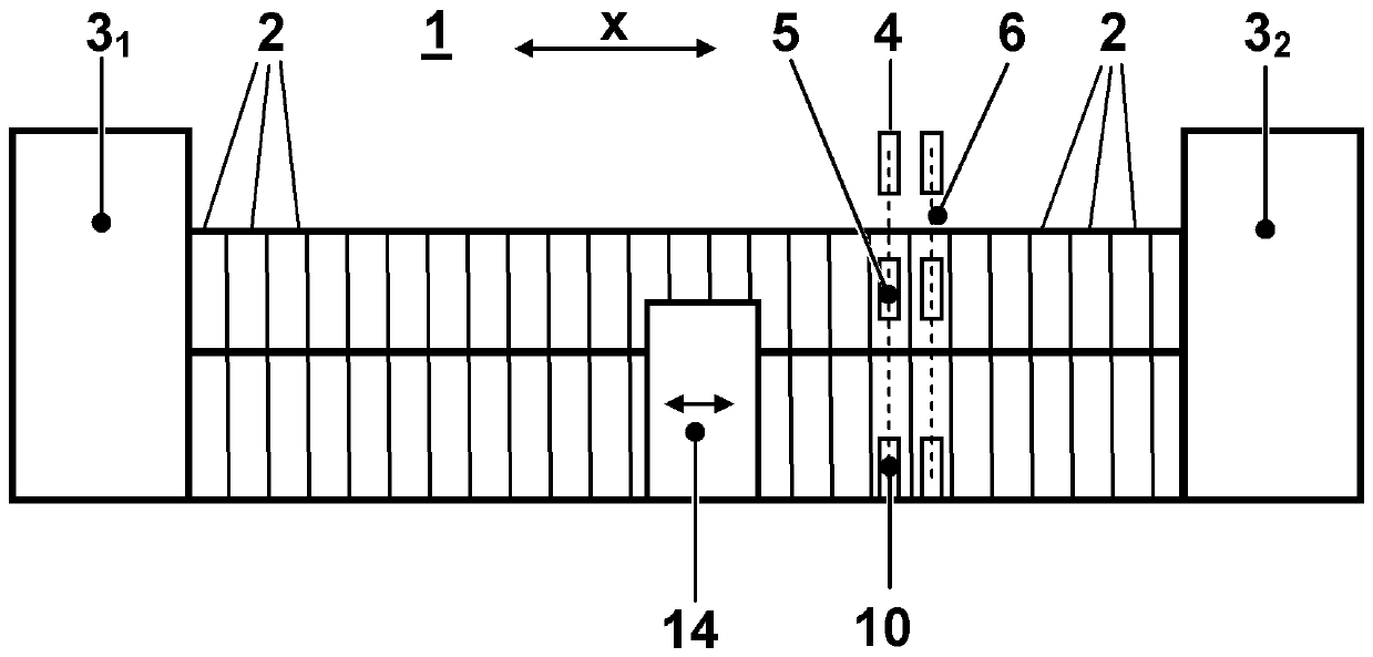
[0051] figure 1 A ring spinning machine 1 according to the invention is shown schematically with a plurality of adjacently positioned spinning stations 2 . The spinning station 2 is located at the head 3 along the longitudinal direction x of the ring spinning machine 1 1 and tail 3 2 between. Head 3 of ring spinning machine 1 1 and tail 3 2 May contain bearings, drives, controllers etc. necessary for operating the spinning machine. For example, as further apparent, in figure 1 with 2 At two spinning ...


PUM


Abstract

A method for operating a ring spinning machine (1) having a service carriage (14) is disclosed, wherein the ring spinning machine (1) has a plurality of spinning stations (2), wherein the spinning stations (2) include a drafting system (5) having a discharge cylinder, a thread guide (7), a balloon control ring (8), a spindle (8), a ring traveller (13), and a spindle monitor (15), and wherein the service carriage (14) moves along the spinning stations (2) on one side of the ring spinning machine (1) and eliminates thread breaks at the spinning stations (2) by means of a standard program. When athread break is detected at a spinning station (2), a status of the spinning station (2) having the thread break is determined in a module (241, 242), and based on the determined status a decision ismade as to whether the thread break can be eliminated by the standard program of the service carriage (14). The invention further relates to a corresponding ring spinning machine (1).

Description

technical field [0001] The invention relates to a method for operating a ring spinning machine, and a corresponding ring spinning machine, according to the preambles of the independent claims. Background technique [0002] Maintenance robots or maintenance stands are known which splice the threads on ring spinning machines after a thread break. Mention is made here in particular of the maintenance robot from EP 394671 A2. The maintenance robot moves along a row of spinning stations, detects thread breaks and then attempts to eliminate the detected thread breaks. The belt driving the spindles is initially lifted from the spindles by means of specific spindle brakes, which are then stopped. Also, use auxiliary lines. One end of the auxiliary wire is fastened to a winder which is movable around the spinning bobbin so that it will then be wound around the spinning bobbin. The auxiliary wire is then threaded through the ring traveler and the wire guide and brought into the re...

Claims


Application Information

Patent Timeline
Patent Type & Authority Applications(China)
IPC IPC(8): D01H15/013D01H13/32
CPCD01H15/013D01H13/32
Inventor P.安德莱格H.卡派勒
Owner MASCHINENFABRIK RIETER AG
Why Eureka
Try Eureka