
Locking device of co2 laser tube and optical equipment for installing the locking device

A locking device and laser tube technology, applied in gas laser parts, laser parts and other directions, can solve the problems of optical path deviation, small contact area, loose CO2 laser tube, etc., and achieve radial adjustment and adaptability. Wide and powerful effects

Active Publication Date: 2020-06-30
WUHAN MIRACLE LASER SYST
View PDF9 Cites 0 Cited by
  • Summary
  • Abstract
  • Description
  • Claims
  • Application Information

AI Technical Summary

Problems solved by technology

[0004] However, on the one hand, when the above-mentioned locking device rotates the nut to tighten the screw, it will slightly drive the screw to rotate, causing a slight change in the output optical path of the CO2 laser tube, thereby affecting the accuracy of the output optical path of the CO2 laser tube; on the other hand, due to The contact area between the screw and the CO2 laser tube is small. If the force exerted by the screw on the CO2 laser tube is small, the CO2 laser tube is easy to loosen, causing the optical path to deviate. If the force exerted by the screw on the CO2 laser tube is large, it is easy to cause CO2 The laser tube is broken. It can be seen that there are many disadvantages in the existing locking device.

Method used


Image

  • Locking device of co2 laser tube and optical equipment for installing the locking device
  • Locking device of co2 laser tube and optical equipment for installing the locking device
  • Locking device of co2 laser tube and optical equipment for installing the locking device

Examples


Embodiment Construction

[0035] The technical solution of each embodiment in the present invention will be clearly and completely described below in conjunction with the accompanying drawings. Apparently, the described embodiments are only part of the embodiments of the present invention, not all of them. Based on the embodiments of the present invention, all other embodiments obtained by persons of ordinary skill in the art without making creative efforts fall within the protection scope of the present invention.

[0036] In the description of the present invention, it should be noted that the terms "center", "upper", "lower", "left", "right", "vertical", "horizontal", "inner", "outer" etc. The indicated orientation or positional relationship is based on the orientation or positional relationship shown in the drawings, and is only for the convenience of describing the present invention and simplifying the description, rather than indicating or implying that the referred device or element must have a s...


PUM


Abstract

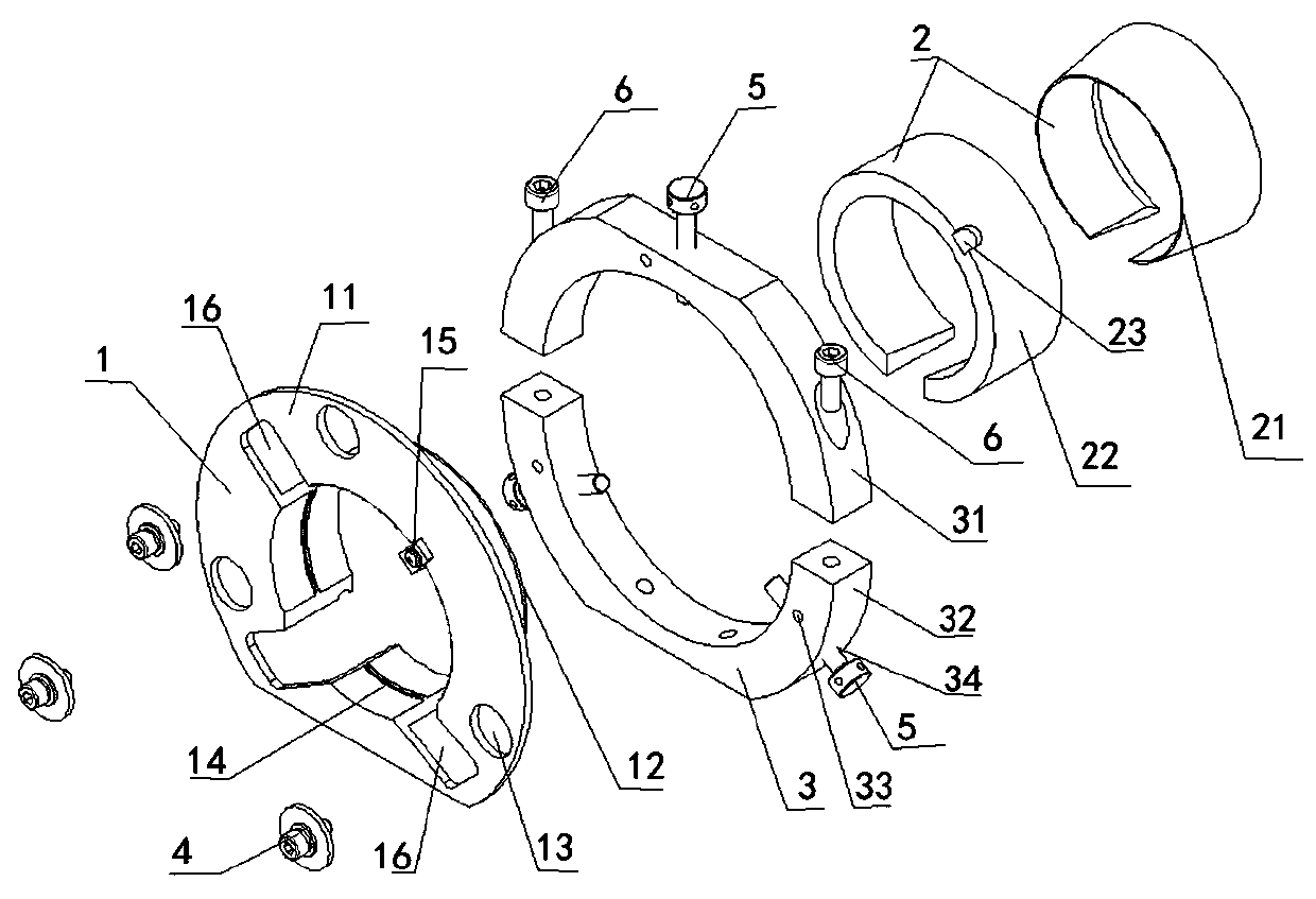
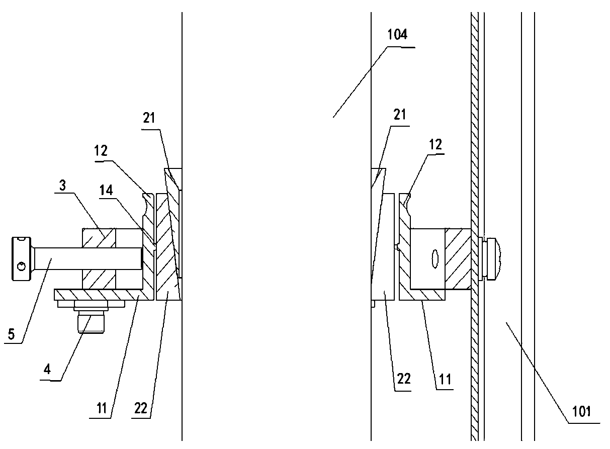
The invention discloses a locking device of a CO2 laser tube and optical equipment provided with the locking device, and relates to the technical field of photoelectricity, the locking device comprises an adjusting ring and an annular positioning ring of an annular clamping part, the adjusting ring comprises a bottom surface and a hollow cylindrical ring surface, and a plurality of limiting holesare formed in the bottom surface; the clamping part is arranged in the annular surface in a sleeving manner and is used for clamping the CO2 laser tube; the positioning ring is arranged on the ring surface in a sleeving manner, the bottom and the bottom surface of the positioning ring are connected through a plurality of first screws, the first screws correspondingly penetrate through one limitinghole, and a certain gap is reserved in the limiting hole by the first screws; meanwhile, the positioning ring is provided with a plurality of second screws, and the second screws penetrate through the positioning ring and abut against the ring surface so as to lock the CO2 laser tube. According to the locking device of the CO2 laser tube, the CO2 laser tube can be locked, and radial adjustment ofthe CO2 laser tube can be achieved.

Description

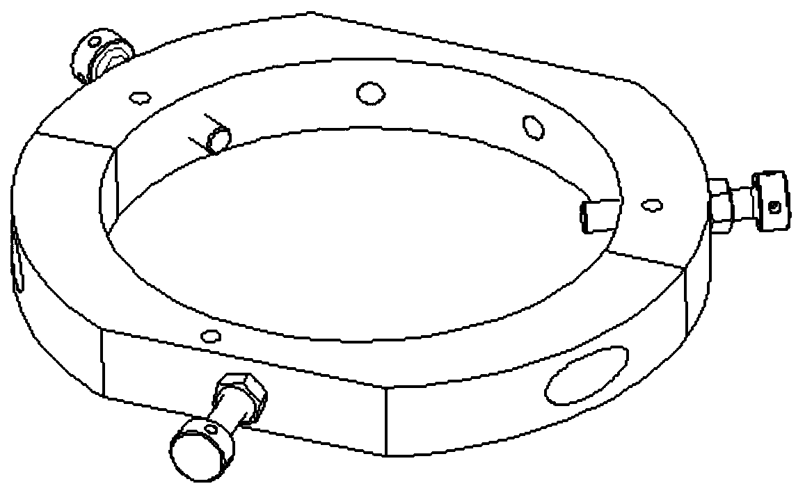
technical field [0001] The invention relates to the field of optoelectronic technology, in particular to a locking device for a CO2 laser tube and optical equipment for installing the locking device. Background technique [0002] CO2 laser has the characteristics of high efficiency and wide application, and is a relatively important gas laser. CO2 lasers are mainly used for cutting, vaporizing, carbonizing, coagulating and irradiating human tissues, and have been widely used in ENT, dermatology, cosmetology, gynecology, neurosurgery and other surgical operations. In the CO2 laser, a locking device is needed to fix the CO2 laser tube and adjust the radial position of the CO2 laser tube. [0003] see figure 1 As shown, the locking device in the prior art usually includes a locking ring, several screws and several nuts that cooperate with the screws. When in use, the CO2 laser tube is placed in the locking ring, and then the position of the screw is adjusted. , so that the e...

Claims


Application Information

Patent Timeline
Patent Type & Authority Patents(China)
IPC IPC(8): H01S3/03
CPCH01S3/03
Inventor 宋忠焕彭国红王晓沛
Owner WUHAN MIRACLE LASER SYST
Learn More