
Flange assembling platform

A flange pairing and platform technology, applied in auxiliary devices, auxiliary welding equipment, welding/cutting auxiliary equipment, etc., can solve the problems of flange welding end face flatness, influence on welding quality, and high labor intensity, etc., to achieve Reasonable structure, guaranteed welding quality and reduced labor intensity

Inactive Publication Date: 2015-06-24
王勇
View PDF6 Cites 0 Cited by
  • Summary
  • Abstract
  • Description
  • Claims
  • Application Information

AI Technical Summary

Problems solved by technology

[0003] The present invention provides a flange assembly platform, which overcomes the deficiencies of the prior art and can effectively solve the problem of spot welding between flanges and cylinder joints. When using an external jack to adjust the radial direction of the cylinder section, the labor intensity is high and the efficiency is low;
[0004] also solves the problem of three-point support method to support the flange, the flatness of the flange welding end surface cannot be guaranteed, and there is an excessive or uneven gap between the groups, which affects the welding quality The problem

Method used


Image

  • Flange assembling platform

Examples


Embodiment Construction

[0018] The present invention is not limited by the following examples, and specific implementation methods can be determined according to the technical solutions of the present invention and actual conditions.

[0019] In the present invention, for the convenience of description, the description of the relative positional relationship of each component is based on the description attached to the description. figure 1 The layout method is described, such as: the positional relationship of top, bottom, left, right, etc. is based on the attached figure 1 determined by the layout direction.

[0020] Below in conjunction with embodiment and accompanying drawing, the present invention will be further described:

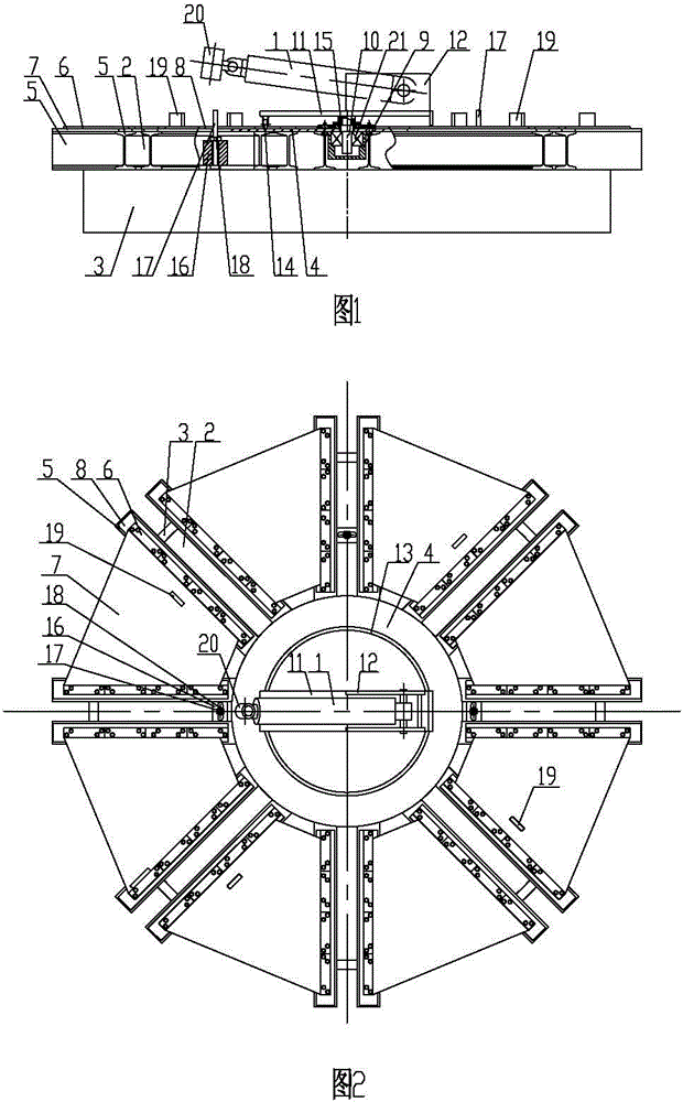
[0021] as attached figure 1 , 2 As shown, the flange assembly platform includes a platform body, a support rotation mechanism, a cylinder mounting seat and a cylinder section internal support pressure cylinder 1; a cylinder mounting seat capable of horizonta...


PUM


Abstract

The invention relates to the technical field of clamping platforms for assembling barrel sections and flanges of tower barrels of wind power generation towers and discloses a flange assembling platform. The flange assembling platform comprises a platform body, a rotary support mechanism, a cylinder body mounting seat and an inner barrel section support pressure cylinder; the cylinder mounting seat which is capable of rotating horizontally is mounted at the middle of the platform body through the rotary support mechanism, and the inner barrel section support pressure cylinder is hinged to the cylinder body mounting seat. The flange assembling platform is reasonable and compact in structure and is convenient to use; when assembling and spot welding the flange and the barrel section, pushing the cylinder body mounting seat and the inner barrel section support pressure cylinder to rotate through manpower, enabling the inner barrel section support pressure cylinder to push the inner circular surface of the barrel section to make the barrel section move lengthwise, so that the lengthwise regulation for the barrel section is realized; the labor intensity is lowered, and the working efficiency is improved; and meanwhile, the platform body which is used for supporting the flange is leveled through a leveling base plate, so that the flatness of the clamping surface of the upper end of the platform body is guaranteed, the flatness of the flange welding head face is guaranteed, the assembling interval is reduced, and the welding quality is guaranteed.

Description

technical field [0001] The invention relates to the technical field of a clamping platform for combining a tube section and a flange of a wind power tower tube, and relates to a flange matching platform. Background technique [0002] The tower tube of the wind power tower is made of multiple tube sections superimposed and welded; each tube section is welded with a steel plate reel, and adjacent tube sections are butted through flange ring seams; in order to make the tube sections and flanges completely For butt jointing, spot welding must be carried out along the circumference before welding the girth seam to ensure the size and position of the flange and the cylinder joint during girth welding; during spot welding, the cylinder joint needs to be adjusted radially according to the position of the welding spot, because The volume and weight of the barrel joint are relatively large. Usually, a jack is used on the outside of the barrel joint. The labor intensity is high and th...

Claims


Application Information

Patent Timeline
Patent Type & Authority Patents(China)
IPC IPC(8): B23K37/04
CPCB23K37/053
Inventor 李众王勇刘春雨郑云徐成春武迎峰
Owner 王勇
Learn More