
Printing equipment for preparing OLED film and printing method thereof

A thin film packaging and equipment technology, applied in the field of OLED automatic production equipment, can solve problems such as low experimental flexibility, low experimental efficiency, experimental methods and innovation limitations.

Active Publication Date: 2020-03-31
SHENZHEN CHINA STAR OPTOELECTRONICS SEMICON DISPLAY TECH CO LTD
View PDF3 Cites 0 Cited by
  • Summary
  • Abstract
  • Description
  • Claims
  • Application Information

AI Technical Summary

Problems solved by technology

[0004] 1. Low experimental efficiency: Due to the long time span of each process, each process requires manual intervention by personnel, resulting in low experimental efficiency and cannot support unmanned production. Multiple groups of experimental products require personnel to follow the production line 24 hours a day
[0005] 2. Poor experimental yield rate: due to personnel delay or misoperation, causing overtime, the glass substrate cannot enter the next process at the best time, which affects the yield rate of experimental products, or makes mistakes or misses the process sequence, increasing Large experiment failure rate
[0006] 3. Low experimental flexibility: Since the software of the equipment manufacturer is not intelligent enough, the production line cannot adapt to various experimental procedures or temporary innovation procedures, and secondary software changes are required, resulting in restrictions on experimental methods and innovations
[0007] 4. Poor confidentiality of the experiment: Since the design of each new process flow requires the equipment manufacturer to modify the software, the experimental logic, experimental ideas, and experimental methods are exposed to the equipment supplier, which does not benefit the confidentiality of the R&D core technology

Method used


Image

  • Printing equipment for preparing OLED film and printing method thereof

Examples


Embodiment Construction

[0023] The technical solutions in the embodiments of the present application will be clearly and completely described below in conjunction with the drawings in the embodiments of the present application. Apparently, the described embodiments are only some of the embodiments of this application, not all of them. Based on the embodiments in this application, all other embodiments obtained by those skilled in the art without making creative efforts belong to the scope of protection of this application.

[0024] In the description of the present application, it should be understood that the terms "center", "longitudinal", "transverse", "length", "width", "thickness", "upper", "lower", "front", " Orientation indicated by rear, left, right, vertical, horizontal, top, bottom, inside, outside, clockwise, counterclockwise, etc. The positional relationship is based on the orientation or positional relationship shown in the drawings, which is only for the convenience of describing the a...


PUM


Abstract

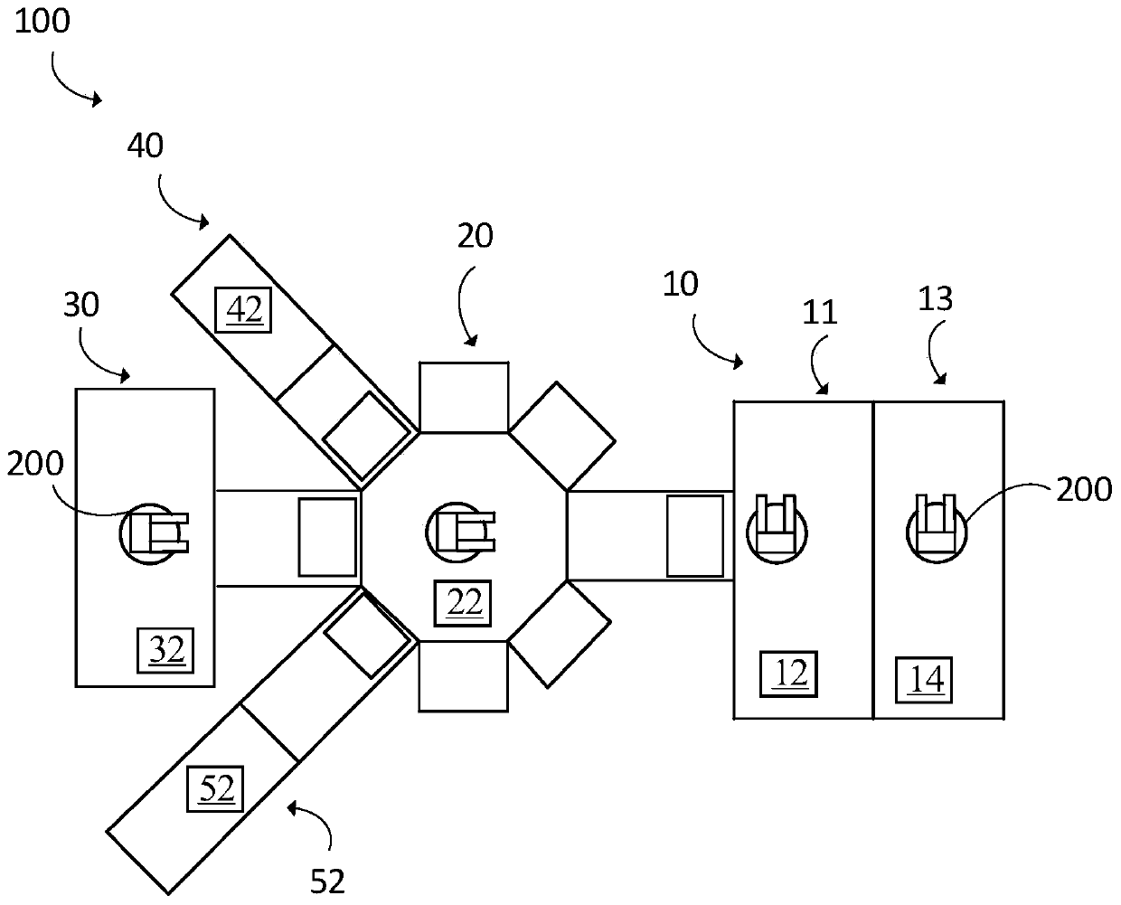
The invention provides an OLED automatic production equipment which comprises evaporation equipment, printing equipment, sputtering equipment, flexible packaging equipment and thin film packaging equipment. The evaporation equipment is used for transferring a glass substrate and comprises a processor. The thin film packaging equipment is used for transferring the glass substrate and comprises a processor. The printing equipment is for transferring the glass substrate and includes a processor. The sputtering equipment is for transferring the glass substrate and includes processors. The flexible packaging equipment is used for transferring the glass substrate and comprises a processor. The thin film packaging equipment communicates with the evaporation equipment, the printing equipment, thesputtering equipment, the flexible packaging equipment and the like. The processors of the evaporation equipment, the printing equipment, the sputtering equipment and the flexible packaging equipmentare used for bidirectional communication with the processor of the thin film packaging equipment. According to the invention, automatic production can be realized, the yield is improved, different production processes can be configured, and the experiment flexibility is improved.

Description

technical field [0001] The disclosure relates to the field of display technology, in particular to an OLED automatic production equipment. Background technique [0002] In the existing technology, the current production mode of OLED equipment requires personnel to manually order the glass substrate to transmit between multiple devices, and passes through multiple complex processes in the middle. According to the experimental case, multiple processes need to be combined. The process is repeated 3-5 times to and fro. [0003] The current production mode of OLED equipment has the following disadvantages: [0004] 1. Low experimental efficiency: Due to the long time span of each process, each process requires manual intervention by personnel, resulting in low experimental efficiency and cannot support unmanned production. Multiple groups of experimental products require personnel to follow the production line 24 hours a day. [0005] 2. Poor experimental yield rate: due to per...

Claims


Application Information

Patent Timeline
Patent Type & Authority Applications(China)
IPC IPC(8): H01L21/67H01L51/56
CPCH01L21/67155H01L21/67276H10K71/00H01L21/67207H01L21/67161H01L21/67167G05B19/4093G05B2219/49023G05B2219/49027
Inventor 王科源
Owner SHENZHEN CHINA STAR OPTOELECTRONICS SEMICON DISPLAY TECH CO LTD
Learn More