
Multifunctional cloth loosening machine

A loose cloth machine, multi-functional technology, applied in textiles and papermaking, transportation and packaging, fabric surface trimming, etc., can solve the problems of reduced production efficiency, single function, unfavorable cutting and processing, etc.

Inactive Publication Date: 2020-03-31
义乌市尼美机械加工厂
View PDF0 Cites 2 Cited by
  • Summary
  • Abstract
  • Description
  • Claims
  • Application Information

AI Technical Summary

Problems solved by technology

[0003] However, the functions of the loosening machine at the present stage are relatively single. When the cloth enters the market, it not only needs to be loosened, but also to perform a series of operations such as cloth inspection. Generally, these processes are independent of each other, and are manually transported. Manual feeding is complicated and cumbersome to operate. After the cloth is packaged and transported, the surface is prone to wrinkles, which increases the instability of the size, which is not conducive to the later cutting process and affects the quality of the product. If it is ironed alone, the The process is increased and the production efficiency is reduced. Therefore, a multifunctional loose cloth machine is proposed to solve the above problems.

Method used


Image

  • Multifunctional cloth loosening machine
  • Multifunctional cloth loosening machine
  • Multifunctional cloth loosening machine

Examples


Embodiment 1

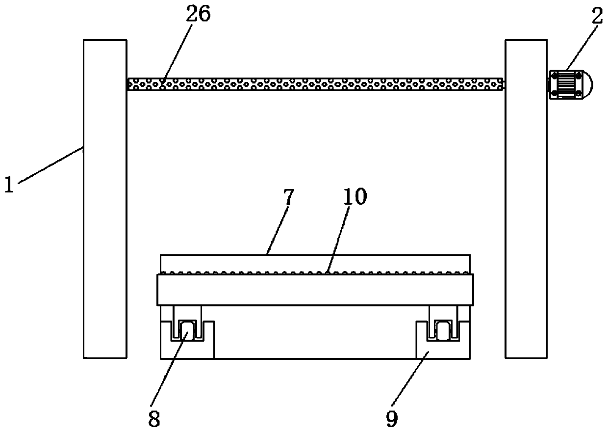
[0026] Embodiment one, with reference to Figure 1-4 , a multi-functional loose cloth machine, comprising a bracket 1 and a platform board 11, a platform board 11 is fixedly installed on the top surface of one side of the bracket 1, the installation height of the platform board 11 is not more than 1.6 meters, and loose cloth is arranged between the inside of the bracket 1 Roller 26 and extrusion roller 27, loose cloth roller 26 connection end runs through support 1 side surface and is connected with the output end of loose cloth roller motor 2 fixedly connected with support 1 side surface, loose cloth roller motor 2 drives loose cloth roller 26 to rotate , and one side of the loose cloth roller 26 is provided with a squeeze roller 27, the surface of the bracket 1 is provided with a moving groove 4, and the inside of the moving groove 4 is slidingly connected with a bearing 5, and the bearing 5 is connected to the inner wall of the moving groove 4 through the first cylinder 3, ...

Embodiment 2

[0027] Embodiment two, refer to figure 1 , the top surface of the platform plate 11 is located between the pressure rollers 12 and is provided with an ironing box 14, and the inside of the ironing box 14 is provided with an ironing board 17, and the bottom surface of the ironing board 17 is provided with an air vent 19, and the top of the ironing board 17 The surface is connected to the inner top surface of the ironing box 14 through the third cylinder 15, and the top surface of the ironing board 17 is located between the third cylinders 15 and is connected with an air inlet 18, wherein the two ends of the ironing board 17 are provided with raised ends 16, and the bottom surface of the ironing board 17 is a smooth structure, and the ironing board 17 and the lifting end 16 are of an integral structure, the lifting end 16 prevents the cloth from being scratched, and is convenient for the cloth to pass through, wherein the air inlet 18 connects the hose and the steam The air outl...

Embodiment 3

[0028]Embodiment three, refer to figure 1 , Loose cloth roller motor 2, drive motor, first cylinder 3, second cylinder 6, third cylinder 15, steam generator are all opened and closed by the control switch control, because the control structure is comparatively common, do not repeat too much here.

[0029] Working principle: move the device to a suitable position, turn on the power for the device, and when inspecting and loosening the cloth, place the cloth roller on the top surface of the carrying roller 25, lead out one end of the cloth roller, bypass the guide roller 23, and Put one end of the cloth roller under the pressure roller 12, start the pressure roller 12, and the pressure roller 12 rotates to drive the cloth to the other end of the platform plate 11 through friction. The lamp 21 illuminates the cloth, and the staff can see the defects of the cloth by standing under the transparent glass 13, and inspect the cloth. At this time, the first cylinder 3 stretches and pu...


PUM


Abstract

The invention discloses a multifunctional cloth loosening machine. The multifunctional cloth loosening machine comprises a support and a platform plate, wherein the platform plate is fixedly mounted on the top surface of the surface of one side of the support, a cloth loosening roller and an extrusion roller are arranged in the support, and the connecting end of the cloth loosening roller penetrates through the surface of one side of the support and is connected with the output end of a cloth loosening roller motor fixedly connected with the surface of one side of the support. According to themultifunctional cloth loosening machine, firstly, a compression roller, an illuminating lamp, transparent glass, the cloth loosening roller and the extrusion roller are adopted, so that the device can perform cloth inspection and cloth loosening work simultaneously, and the working efficiency is greatly improved; meanwhile, a worker only needs to wind cloth around the surface of a guide roller and place the cloth below the compression roller, then the installation can be completed, and the installation is extremely convenient; secondly, an ironing box is adopted, the cloth penetrates throughthe ironing box to be ironed, and the surface of the cloth is guaranteed to be flat; and the device integrates the ironing function, the cloth is ironed during cloth inspection and cloth loosening, the later process is reduced, and the production efficiency is greatly improved.

Description

technical field [0001] The invention relates to the technical field of textile equipment, in particular to a multifunctional loom. Background technique [0002] The original meaning of textile is taken from the general term of spinning and weaving, but with the continuous development and improvement of the textile knowledge system and subject system, especially after the emergence of non-woven textile materials and three-dimensional composite weaving technologies, the current textile is not only a traditional Hand spinning and weaving also include non-woven fabric technology, modern three-dimensional weaving technology, modern electrostatic nano-netting technology and other textiles for clothing, industry and decoration. In textile equipment, loose cloth machines are widely used , basically large and small textile mills will be equipped with loose cloth machines, which will fold the rolls of cloth after processing, which is convenient for later production and use. [0003] ...

Claims


Application Information

Patent Timeline
IPC IPC(8): D06H3/06D06C15/00D06B1/08B65H18/10
CPCB65H18/103D06B1/08D06C15/00D06C2700/13D06H3/06
Inventor 乔辉王起任大龙
Owner 义乌市尼美机械加工厂
Learn More