An electronic automatic stop device for reel machine

A wire reel machine, electronic technology, applied in the direction of transportation and packaging, thin material handling, transportation of filamentous materials, etc., can solve the problems of affecting the quality of the wire harness, wasting human resources of the enterprise, affecting the production efficiency of the reel machine, etc. Improve stopping efficiency and ensure the effect of stopping

Active Publication Date: 2021-02-09
泰州市赛鸥网业有限公司
View PDF6 Cites 0 Cited by
  • Summary
  • Abstract
  • Description
  • Claims
  • Application Information

AI Technical Summary

Problems solved by technology

[0002] The wire reel machine is a machine used to curl and coil the wire harness. It is often used for the storage of the wire harness. The existing wire reel device cannot detect when the wire harness is wound up during the winding process, causing the wire reel to still rotate at a high speed. Automatically stop working. The whole working process of the traditional wire reel machine requires textile workers to pay attention to the work of the wire reel machine at all times, which greatly affects the production efficiency of the wire reel machine and wastes the human resources of the enterprise. Some wire reel machines will be set to automatically stop equipment to prevent the wire harness from being damaged due to the wrong work of the wire reel machine, but when the wire reel machine stops working, the wire reel roller will still continue to rotate for a certain distance due to inertia, which will affect the quality of the wire harness

Method used


Image

  • An electronic automatic stop device for reel machine
  • An electronic automatic stop device for reel machine
  • An electronic automatic stop device for reel machine

Examples


Embodiment Construction

[0025] The following will clearly and completely describe the technical solutions in the embodiments of the present invention with reference to the accompanying drawings in the embodiments of the present invention. Obviously, the described embodiments are only some, not all, embodiments of the present invention. Based on the embodiments of the present invention, all other embodiments obtained by persons of ordinary skill in the art without making creative efforts belong to the protection scope of the present invention.

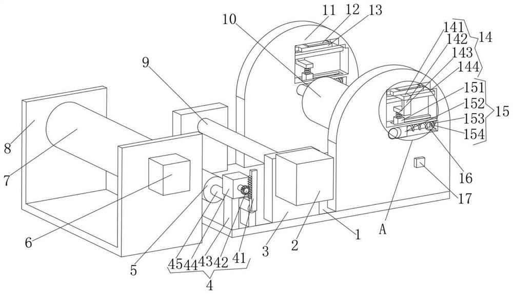
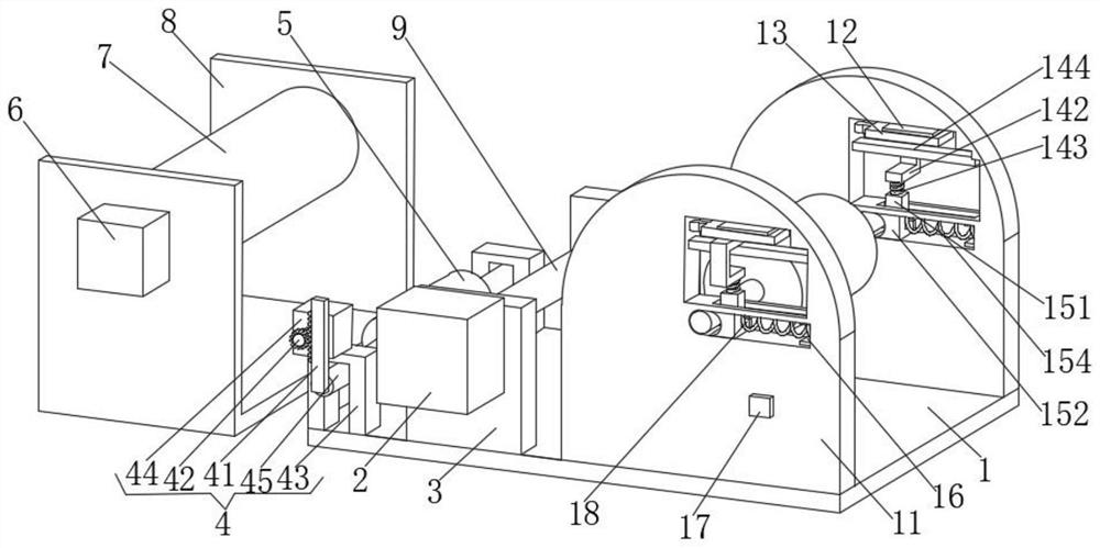
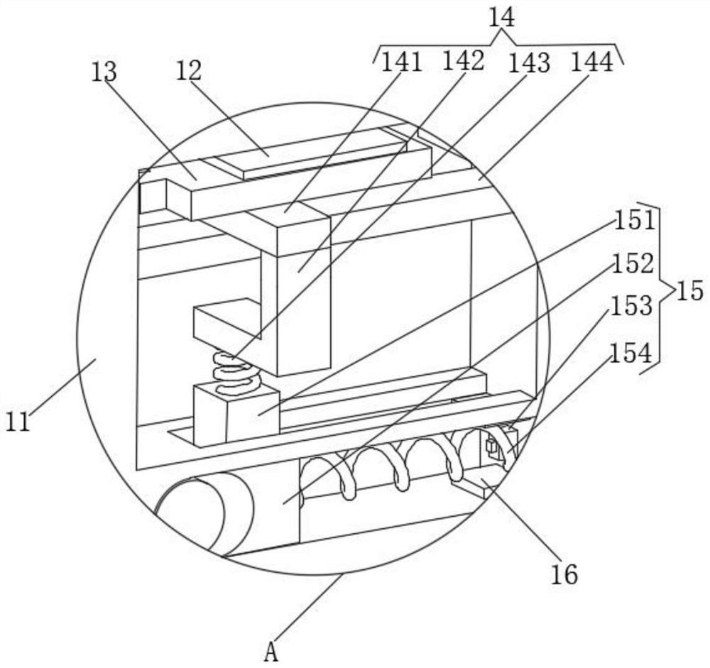
[0026] see Figure 1-3 , the present invention provides a technical solution: an electronic automatic stop device for a reel machine, including a base plate 1, a reel machine base 8, a stop unit 14 and a trigger unit 15;

[0027]The upper side of the bottom plate 1 is fixedly connected with two right side plates 11, the right side plates 11 are symmetrically arranged on the upper side of the bottom plate 1, the right side plate 11 is provided with a top column...


PUM


Abstract

The invention discloses an automatic stopping device for an electronic wire coil machine. The device comprises a baseplate, a wire coil machine base, stopping units and triggering units. Two right side plates are fixedly connected to the upper side of the baseplate and symmetrically arranged on the upper side of the baseplate, a top column horizontal movement groove is formed in one right side plate, a wire placement groove is formed in the other right side plate, and a movement column placement groove is formed between the top column horizontal movement groove and the wire placement groove. Arotation shaft for stopping is movably connected into the top column horizontal movement groove, and the middle of the rotation shaft for stopping is rotatably connected to the center of a stopping roller. The automatic stopping device for the electronic wire coil machine can automatically stop the wire coil machine when the wire coil machine fails first, and then returns a part of wires after stopping is performed to guarantee that the non-coiled wires are prevented from being snapped due to inertia rotation of the wire coil roller and to guarantee that the returned wires are prevented frombeing snapped. Multiple stopping devices are arranged to guarantee the stopping effect.

Description

technical field [0001] The invention relates to the technical field of wire reel machines, in particular to an electronic automatic stop device for wire reel machines. Background technique [0002] The wire reel machine is a machine used to curl and coil the wire harness. It is often used for the storage of the wire harness. The existing wire reel device cannot detect when the wire harness is wound up during the winding process, causing the wire reel to still rotate at a high speed. Automatically stop working. The whole working process of the traditional wire reel machine requires textile workers to pay attention to the work of the wire reel machine at all times, which greatly affects the production efficiency of the wire reel machine and wastes the human resources of the enterprise. Some wire reel machines will be set to automatically stop The equipment prevents the wire harness from being damaged due to the wrong work of the wire reel machine, but when the wire reel machin...

Claims


Application Information

Patent Timeline
Patent Type & Authority Patents(China)
IPC IPC(8): B65H75/30
CPCB65H54/74B65H75/30
Inventor 张大涌
Owner 泰州市赛鸥网业有限公司
Why Eureka
Try Eureka