
A blood collection test tube placement rack

A blood collection and placement rack technology, applied in the direction of test tube brackets/clamps, etc., can solve the problems of blocking laboratory personnel, inconvenient access to test tubes, broken test tubes, etc., and achieves the effect of simple structure.

Inactive Publication Date: 2021-06-15
JILIN UNIV
View PDF0 Cites 0 Cited by
  • Summary
  • Abstract
  • Description
  • Claims
  • Application Information

AI Technical Summary

Problems solved by technology

[0002] The collection test tube rack is used to place test tubes, which is a standing equipment in medical treatment; the general test tube rack is composed of a base plate, a support plate and a guardrail, and a placement hole is opened on the guardrail, and the test tube can be inserted into it; medical staff will place it after collecting blood from the patient On the test tube rack, and then sent to the laboratory, the general placement is fixed, sometimes blocking the sight of the laboratory personnel, the laboratory personnel need to pick up the test tube to clearly check the label of the test tube, and the placement holes on the test tube rack are arranged in a rectangular array , the test tube in the middle is inconvenient to take and it is easy to take it wrong; and the general test tube rack does not have the function of fixing the test tube. Once the test tube rack is overturned, the test tube is easy to break; , and it is convenient to observe and take out the test tube rack

Method used


Image

  • A blood collection test tube placement rack
  • A blood collection test tube placement rack
  • A blood collection test tube placement rack

Examples


Embodiment Construction

[0022] The present invention will be further described below in conjunction with accompanying drawing description and specific embodiment:

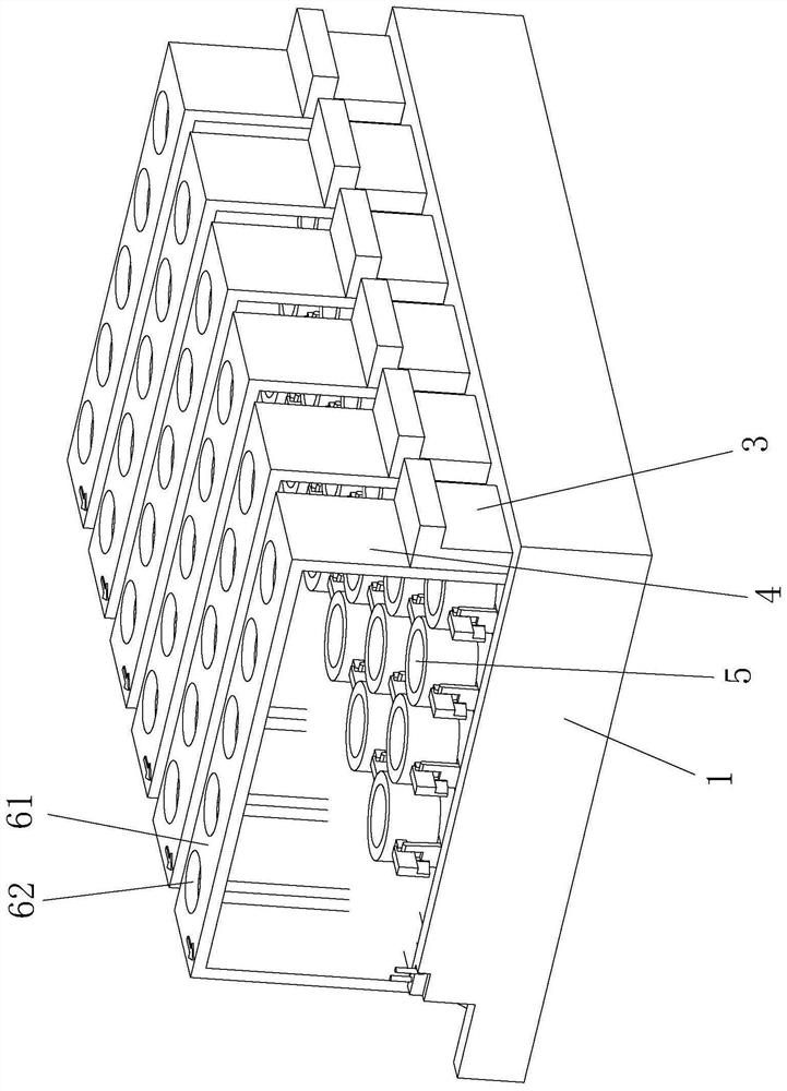
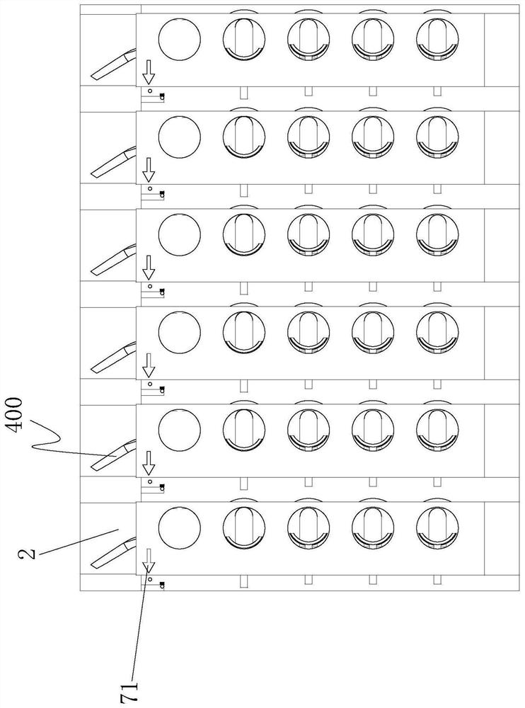
[0023] Such as Figures 1 to 8 A blood collection test tube placement rack shown, its specific implementation is as follows: includes a base 1, a plurality of horizontal chute 2 is evenly spaced on the base 1, and is movable in the horizontal chute 2 There is a moving plate 3, and a test tube rack body 4 is installed in rotation on one side of the moving plate 3. There are a plurality of placing holes 5 for placing test tubes, a flat plate 61 is arranged on the upper end of the test tube holder body 4, and circular holes 62 corresponding to the placing holes 5 are arranged at intervals on the flat plate 61, and on the flat plate 61 The upper surface of 61 is provided with a prompt arrow 71 for prompting the placement direction of the label. The direction of the label of the test tube is consistent with the direction of the prompt arrow 7...


PUM


Abstract

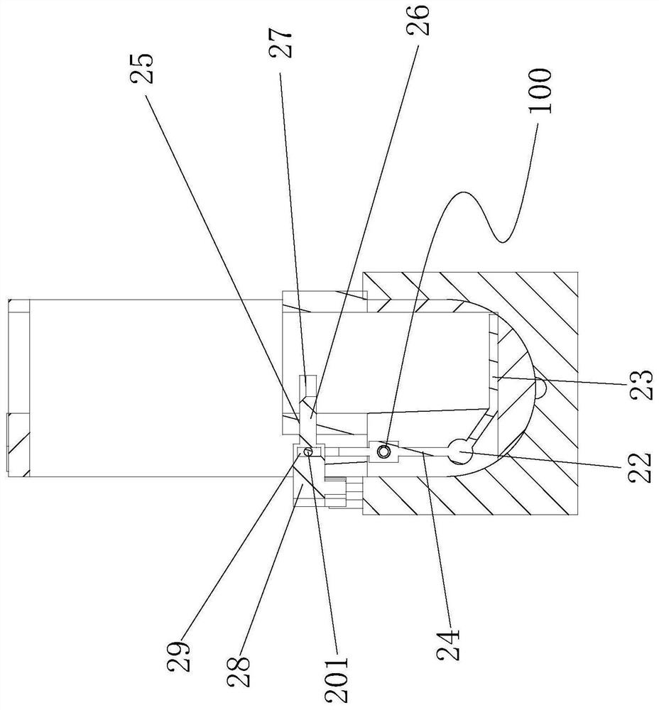
The invention discloses a blood collection test tube placement rack, which includes a base, and a plurality of horizontal chutes are evenly spaced on the base, and a moving plate is movable in the horizontal chute. A test tube rack body is installed on the side rotation, and the two sides of the test tube rack body are attached to the inner wall of the transverse chute. A plurality of placement holes for placing test tubes are evenly spaced on the test tube rack body. A locking mechanism that can lock the test tube is provided inside, and a transmission mechanism that can drive the test tube rack to turn when the moving plate moves along the horizontal chute is provided on the horizontal chute. The unlocking mechanism that unlocks the locking mechanism by moving the test tube rack outward along the transverse chute, and the locking mechanism that can lock the locking mechanism by moving the test tube rack inward along the transverse chute on the base The mechanism, according to such a structure, places the test tube in the placement hole, and directly locks the test tube through the locking mechanism.

Description

technical field [0001] The invention relates to a blood collection test tube placement rack. Background technique [0002] The collection test tube rack is used to place test tubes, which is a standing equipment in medical treatment; the general test tube rack is composed of a base plate, a support plate and a guardrail, and a placement hole is opened on the guardrail, and the test tube can be inserted into it; medical staff will place it after collecting blood from the patient On the test tube rack, and then sent to the laboratory, the general placement is fixed, sometimes blocking the sight of the laboratory personnel, the laboratory personnel need to pick up the test tube to clearly check the label of the test tube, and the placement holes on the test tube rack are arranged in a rectangular array , the test tube in the middle is inconvenient to take and it is easy to take it wrong; and the general test tube rack does not have the function of fixing the test tube. Once the...

Claims


Application Information

Patent Timeline
Patent Type & Authority Patents(China)
IPC IPC(8): B01L9/06
CPCB01L9/06
Inventor 黄哲浩李香兰贾玉玺邓力源
Owner JILIN UNIV
Learn More