Intelligent rotary dining table and working method thereof
A rotating dining table, intelligent technology, applied in the dining table field, can solve the problem of inconvenient rotating state of the desktop, and achieve the effects of low strength, increase the rotation speed of the magnet, and increase the detection accuracy
- Summary
- Abstract
- Description
- Claims
- Application Information
AI Technical Summary
Problems solved by technology
Method used
Image
Examples
Embodiment 1
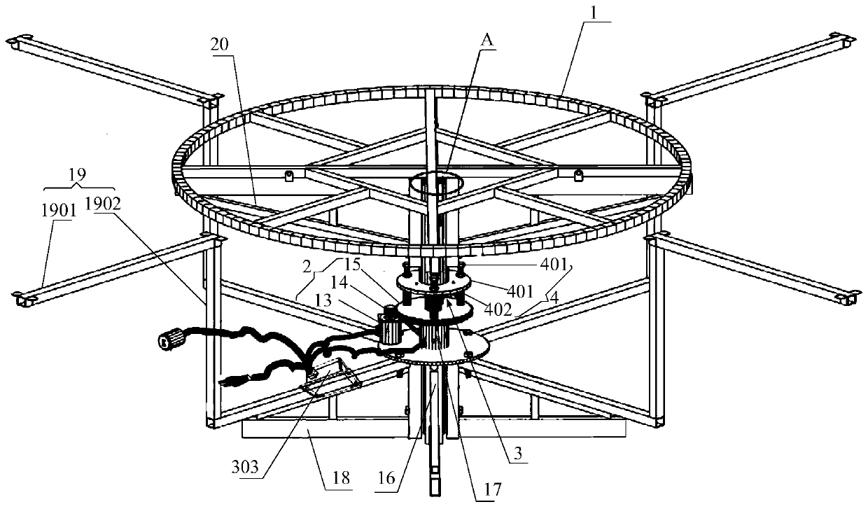
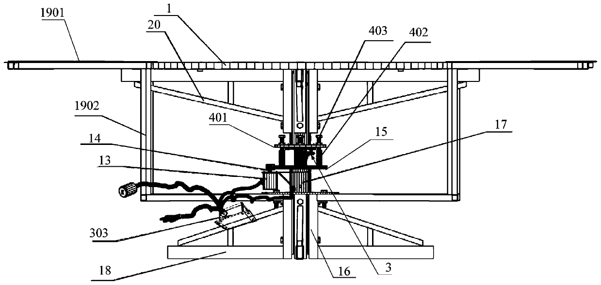
[0057] Such as Figure 1~10 As shown, the intelligent rotating table provided by this embodiment includes a rotating table support 1, a rotating mechanism 2, a table rotation angle measuring mechanism 3, and a clutch mechanism 4 for driving and separating the rotating table support 1 from the rotating mechanism 2.
[0058] The center of the bottom surface of the rotating desktop support 1 is fixedly connected to the clutch mechanism 4 through a sleeve shaft 5, and the clutch mechanism 4 is fixed on the rotating end of the rotating mechanism 2.
[0059] The desktop rotation angle measuring mechanism 3 includes a magnet 301, a magnetic sensitive angle sensor 302, and a controller 303, wherein the magnet 301 is fixed on the clutch mechanism 4 and rotates with the clutch mechanism 4, the magnetic sensitive The angle sensor 302 is located directly below the magnet 301 and remains stationary.
[0060] The magnetic angle sensor 302 is communicatively connected to the input end of the contr...
Embodiment 2
[0095] Such as Figure 1~10 As shown, this embodiment is a specific implementation of the smart rotating table described in the first embodiment, that is, a detailed schematic diagram of the results of each mechanism is provided.
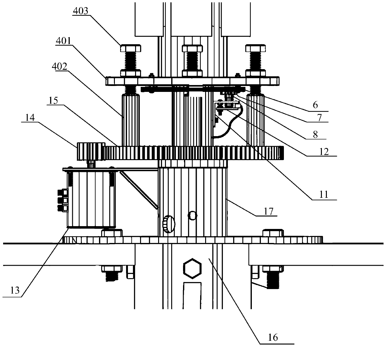
[0096] First, like image 3 As shown, this embodiment provides a schematic diagram of a specific mechanism of the clutch mechanism 4.
[0097] Optimally, the clutch mechanism 4 includes a mounting plate 401, a number of clutch friction columns 402 and a number of adjustment studs 403.
[0098] The top surface of the mounting disk 401 is fixedly connected to the end of the sleeve shaft 5 away from the rotating table support 1, and a plurality of adjusting studs 403 are circumferentially arranged on the top surface of the mounting disk 401.
[0099] The clutch friction column 402 is fixed on the rotating end of the rotating mechanism 2, and the number of the clutch friction column 402 and the adjustment stud 403 are the same, and the positions correspond to e...
Embodiment 3
[0134] Such as Picture 10 As shown, this embodiment is the working method of the intelligent rotating table in the first or second embodiment, and includes the following steps:
[0135] S101. Define variables a, b, c, and d, and assign initial values to 0 respectively.
[0136] S102. The controller obtains the first data input by the magnetic angle sensor and determines whether the first data is valid. If it is valid, execute step S103; otherwise, obtain the next data input by the magnetic angle sensor after a preset time. Until the controller judges that the data is valid.
[0137] S103. The controller assigns the value of the first data to the variable a, and receives the second data from the magnetic angle sensor after a preset time.
[0138] S104. The controller judges whether the second data is valid. If it is valid, it assigns the value of variable a to variable b, and then assigns the value of the second data to variable a, and then receives the input from the magnetic angle...
PUM
 Abstract
Description
Claims
Application Information
 - R&D
- Intellectual Property
- Life Sciences
- Materials
- Tech Scout
- Unparalleled Data Quality
- Higher Quality Content
- 60% Fewer Hallucinations
Browse by: Latest US Patents, China's latest patents, Technical Efficacy Thesaurus, Application Domain, Technology Topic, Popular Technical Reports.
© 2025 PatSnap. All rights reserved.Legal|Privacy policy|Modern Slavery Act Transparency Statement|Sitemap|About US| Contact US: help@patsnap.com


