
High-voltage interface protection device of electrical control cabinet

A technology for electrical control cabinets and high-voltage interfaces, which is applied in the field of high-voltage interface protection devices, and can solve problems such as electric shock, opening, and troublesome use of operators

Inactive Publication Date: 2020-03-27
温州易正科技有限公司
View PDF3 Cites 2 Cited by
  • Summary
  • Abstract
  • Description
  • Claims
  • Application Information

AI Technical Summary

Problems solved by technology

The high-voltage interface in the control cabinet is used to connect to the high-voltage line, but the connection between the high-voltage line and the high-voltage interface will be disconnected before assembly or during maintenance, so that the high-voltage interface is exposed, which is likely to cause fatal electric shock to the operator sexual harm
In order to prevent the operator from getting an electric shock during the construction process, the existing solution is to install a simple board in front of the high-voltage interface to block it, but if the existing board is not fixedly installed, it will easily skew or fall down, so that the high-voltage interface will still be open , and if the board is fixed, it will cause the board to be disassembled when the high-voltage line needs to be connected later, which is troublesome to use and needs to be improved

Method used


Image

  • High-voltage interface protection device of electrical control cabinet
  • High-voltage interface protection device of electrical control cabinet
  • High-voltage interface protection device of electrical control cabinet

Examples


Embodiment Construction

[0018] The specific implementation manners of the present invention will be further described in detail below in conjunction with the accompanying drawings and embodiments. The following examples are used to illustrate the present invention, but are not intended to limit the scope of the present invention.

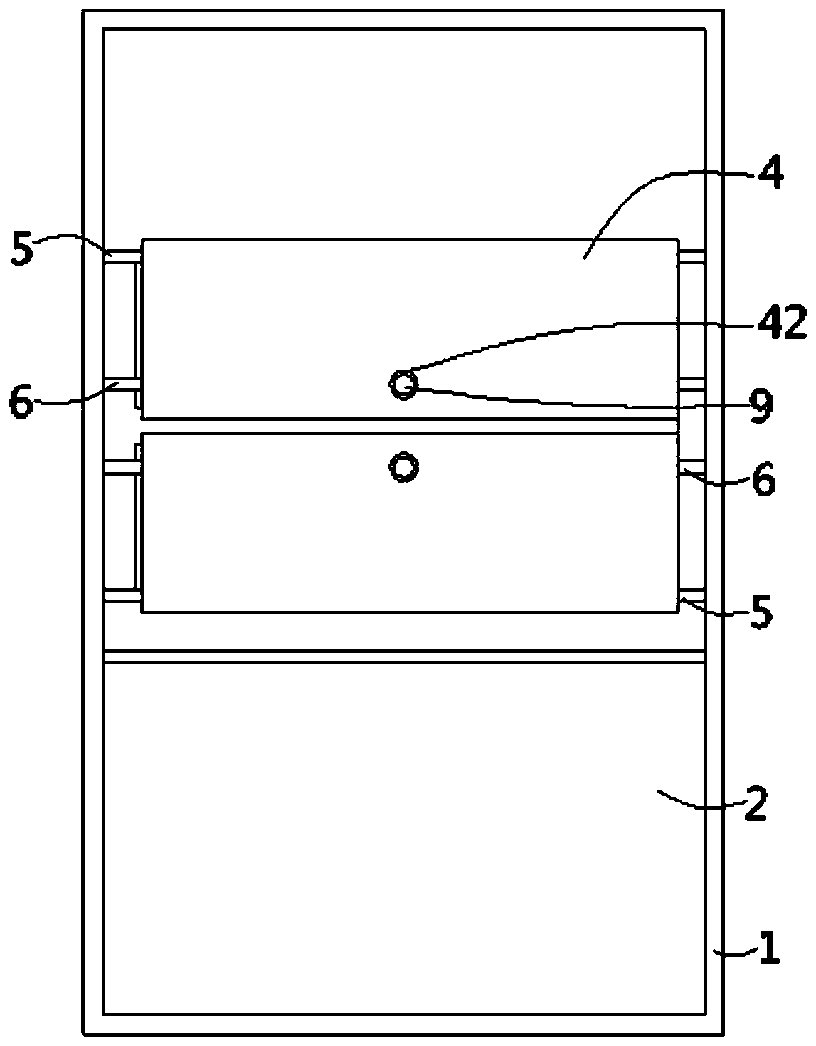
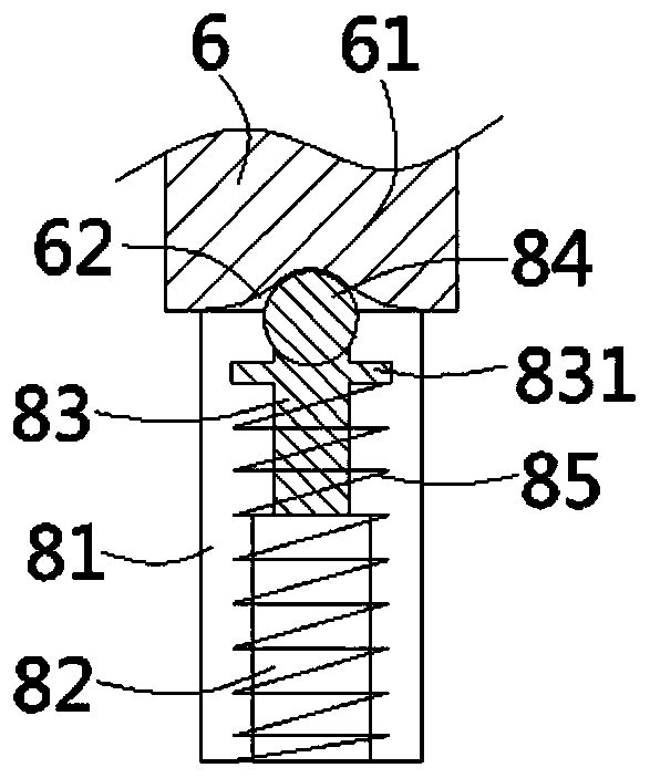
[0019] The following content reference Figure 1 to Figure 4 .

[0020] A high-voltage interface protection device for an electrical control cabinet according to the present invention includes a cabinet body 1, a partition 2 is fixed in the cabinet, and a plurality of through holes 21 are arranged on the partition, and the through holes are plugged with An insulating spacer 3 for fixing the high-voltage joint is fixed, and a cover plate 4 is provided outside the partition on one side of the insulating spacer. The upper and lower ends of the folded edges on the side and the right side are respectively inserted and fixed with a horizontal fixed support shaft 5 and a movabl...


PUM


Abstract

The invention discloses a high-voltage interface protection device of an electrical control cabinet. The device comprises a cabinet body, a partition plate is fixed in cabinet body, an insulating spacer sleeve is inserted into the partition plate; a cover plate is arranged outside the partition plate on one side of the insulating spacer sleeve; a transverse fixed supporting shaft and a transversemovable supporting shaft or a transverse movable supporting shaft and a transverse fixed supporting shaft are respectively inserted and fixed at the upper end and the lower end of the cover plate; arc-shaped guide grooves are formed in the inner walls of the two sides of the cabinet body. The two ends of the movable supporting shaft are inserted into the guide grooves; limiting pieces of the movable supporting shaft are arranged at the two ends of the guide groove. The limiting piece comprises a placement groove formed in the inner wall of the guide groove, an insertion pipe formed in the inner wall of the placement groove, a telescopic rod inserted into the insertion pipe, a ball formed at one end of the telescopic rod and a pressure spring inserted into the telescopic rod and the insertion pipe in a sleeving manner; a baffle is formed on the telescopic rod on one side of the ball, arc-shaped grooves are formed in the two ends of the movable supporting shaft, and one end of the ball is embedded in the corresponding groove. The cover plate can be opened and closed conveniently, and positioning can be achieved when the cover plate is opened and closed.

Description

technical field [0001] The invention relates to the technical field of electrical connectors, in particular to a high-voltage interface protection device for an electrical control cabinet. Background technique [0002] The switch control cabinet is a kind of electrical equipment, and its main function is to switch, control and protect electrical equipment during the process of power generation, transmission, distribution and power conversion in the power system. The outside line of the switch control cabinet first enters the main control switch in the cabinet, and then enters the sub-control switch, and each branch is set according to its needs. The high-voltage interface in the control cabinet is used to connect to the high-voltage line, but the connection between the high-voltage line and the high-voltage interface will be disconnected before assembly or during maintenance, so that the high-voltage interface is exposed, which is likely to cause fatal electric shock to the ...

Claims


Application Information

Patent Timeline
Patent Type & Authority Applications(China)
IPC IPC(8): H02B1/14
CPCH02B1/14
Inventor 徐标
Owner 温州易正科技有限公司
Learn More