Rotary contactor
A contactor, rotary technology, applied in relays, electromagnetic relays, electromagnetic relay details, etc., can solve problems such as low work efficiency, damage to electronic components, and potential safety hazards, to improve service life, improve work efficiency, The effect of reducing workload
- Summary
- Abstract
- Description
- Claims
- Application Information
AI Technical Summary
Problems solved by technology
Method used
Image
Examples
Embodiment 1
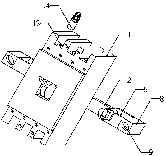
[0022] Such as Figure 1-Figure 3 As shown, a rotary contactor includes a contactor body 1, a plurality of wiring holes 13 are opened on the top of the contactor body 1, and a sealing structure is provided inside the plurality of wiring holes 13, and the sealing structure provided can prevent Water and dust enter the contactor body 1, which is beneficial to protect the electronic components inside the contactor body 1, improve the service life of the electronic components, and avoid short circuits at the same time. Both ends of one side of the contactor body 1 are hinged with connecting plates 2. One end of the two connecting plates 2 is provided with an adjustment structure. The adjustment structure can adjust the angle of the contactor body 1 without removing the contactor body 1, which is convenient for the operator to adjust the contactor body. 1 for maintenance.
Embodiment 2
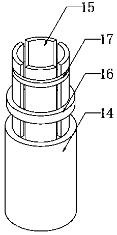
[0024] On the basis of Embodiment 1, such as figure 1 and image 3 As shown, the sealing structure includes a threaded pipe 14 that is threadedly connected with the wiring hole 13, and the top of the threaded pipe 14 is fixedly provided with a plurality of sealing half-rings 15, the material of the sealing half-rings 15 is rubber, and the radius of the top of the sealing half-rings 15 is larger than The radius of the bottom, the top of the outer wall of a plurality of sealing half-rings 15 is provided with a draw-in groove 17, the bottom of the outer wall of a plurality of sealing half-rings 15 is slidably connected with a snap ring 16, and the size of the snap ring 16 matches the size of the draw-in groove 17 , pass the wire through the threaded tube 14 and connect it to the contactor body 1, then tighten the threaded tube 14 to the wiring hole 13, slide the snap ring 16 from the bottom to the inside of the slot 17, tighten the sealing half ring 15, and seal The half-ring 15...
Embodiment 3
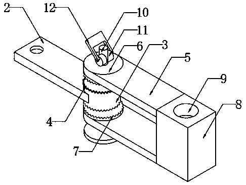
[0026] On the basis of embodiment one and embodiment two, such as figure 1 and figure 2 As shown, the adjustment structure includes two uprights 3 fixedly arranged on one end of the connecting plate 2 respectively, the top and bottom ends of the two uprights 3 are fixedly provided with a first toothed chainset 4, and the two first toothed chainsets 4 Respectively engage and connect with the corresponding second toothed chainsets 7, through the engagement of the first toothed chainsets 4 and the second toothed chainsets 7, the fixing of the connecting plate 2 can be realized, and the two second toothed chainsets 7 are respectively fixedly installed on the bottom end and the top end of the corresponding disc 6, and the two discs 6 are respectively fixedly installed on the top end of one side of the corresponding elastic plate 5 and the bottom end of one side, and one end of the two elastic plates 5 is connected with the connecting block respectively. The bottom and top of one ...
PUM
 Abstract
Description
Claims
Application Information
 - Generate Ideas
- Intellectual Property
- Life Sciences
- Materials
- Tech Scout
- Unparalleled Data Quality
- Higher Quality Content
- 60% Fewer Hallucinations
Browse by: Latest US Patents, China's latest patents, Technical Efficacy Thesaurus, Application Domain, Technology Topic, Popular Technical Reports.
© 2025 PatSnap. All rights reserved.Legal|Privacy policy|Modern Slavery Act Transparency Statement|Sitemap|About US| Contact US: help@patsnap.com


