Air supply control method for a two-stage compression air supply air conditioning system
A two-stage compression and air-conditioning system technology, applied in heating and ventilation control systems, heating and ventilation safety systems, refrigerators, etc., can solve the problem that the amount of supplementary air cannot be adjusted according to working conditions, and achieve the purpose of improving flexibility and reliability Effect
- Summary
- Abstract
- Description
- Claims
- Application Information
AI Technical Summary
Problems solved by technology
Method used
Image
Examples
Embodiment 1
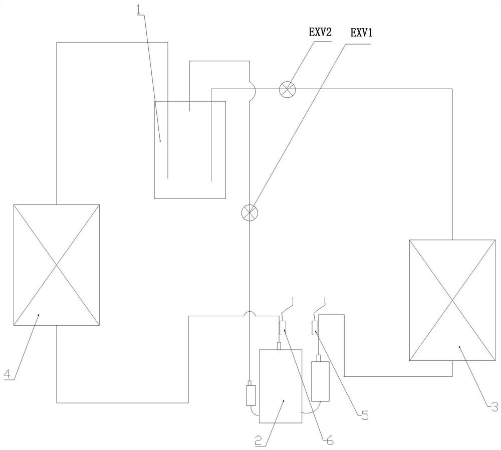
[0050] Such as figure 1 As shown, the present invention provides a high-temperature enthalpy injection refrigeration system (single cooler), including an evaporator 3, a condenser 4, a compressor 2, a flash tank 1, an electronic expansion valve EXV1 and an electronic expansion valve EXV2, as well as exhaust temperature sensor 6 and suction temperature sensor 5. Among them, the flash tank 1 is between the evaporator 3 and the condenser 4, and the electronic expansion valve EXV1 mainly controls the air supply volume, one end of which is connected to the outlet of the flash tank 1, and the other end is connected to the air supply port of the compressor 2; EXV2 mainly controls Exhaust temperature, one end of which is connected to the outlet of flash tank 1, and the other end is connected to the inlet pipe of evaporator 3.
[0051] When air supply control is required, the air supply electronic expansion valve EXV1 is controlled according to the target suction superheat (or target ...
Embodiment 2
[0055] The difference between embodiment 2 and embodiment 1 is that the four-way valve 7 and the third valve body (electronic expansion valve EXV3) are added.
[0056] Such as figure 2 As shown, the present invention provides a high-temperature enthalpy injection refrigeration system (heat pump machine), including an evaporator 3, a condenser 4, a compressor 2, a flash tank 1, a four-way valve 7, three electronic Expansion valves EXV1, EXV2 and EXV3, as well as discharge temperature sensor 6 and suction temperature sensor 5.
[0057] During refrigeration operation: the cooled refrigerant from the outlet of condenser 4 flows into flash tank 1 after passing through EXV3, and the steam from flash tank 1 flows into compressor 2 after passing through electronic expansion valve EXV1 to control the amount of supplementary air Air supply port; another subcooled refrigerant from the flash tank 1 flows into EXV2 for throttling, and after throttling, the saturated refrigerant flows int...
Embodiment 3
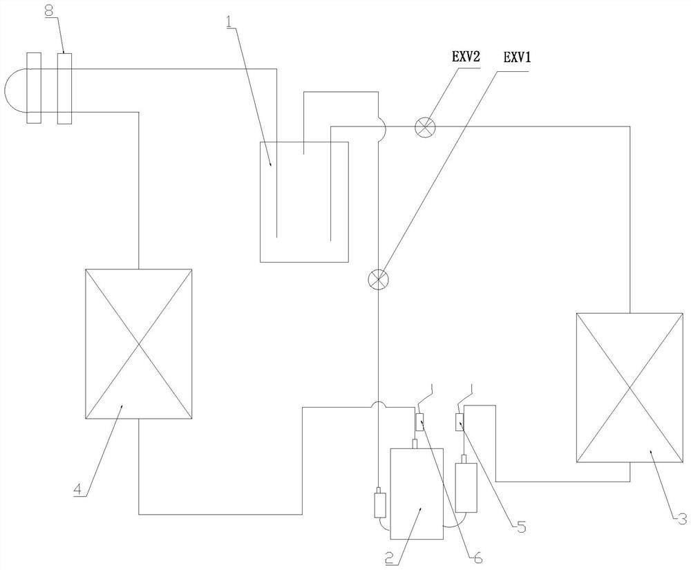
[0061] Such as image 3 As shown, the present invention provides a high-temperature enthalpy injection refrigeration system (single cooler) with refrigerant pipe cooling, and compared with Embodiment 1, a refrigerant pipe cooling device 8 is added.
[0062] The high-temperature enthalpy injection refrigeration system includes an evaporator 3, a condenser 4, a compressor 2, a flash tank 1, a refrigerant pipe cooling device 8, electronic expansion valves EXV1 and EXV2, and an exhaust temperature sensing package 6 and suction Air sensor temperature pack 5. Among them, the refrigerant pipe cooling device 8 is on the outlet pipe of the condenser 4, and the electronic expansion valve EXV1 is mainly used to control the air supply volume, one end of which is connected to the outlet of the flash tank 1, and the other end is connected to the air supply port of the compressor 2; EXV2 mainly controls the exhaust temperature, one end is connected to the outlet of flash tank 1, and the oth...
PUM
 Abstract
Description
Claims
Application Information
 - R&D
- Intellectual Property
- Life Sciences
- Materials
- Tech Scout
- Unparalleled Data Quality
- Higher Quality Content
- 60% Fewer Hallucinations
Browse by: Latest US Patents, China's latest patents, Technical Efficacy Thesaurus, Application Domain, Technology Topic, Popular Technical Reports.
© 2025 PatSnap. All rights reserved.Legal|Privacy policy|Modern Slavery Act Transparency Statement|Sitemap|About US| Contact US: help@patsnap.com


