


Quick Research
Generate reliable direction feasibility study reports for your R&D in just a few steps.

Technical Q&A
Discover and master advanced knowledge NOW. Basics, ideas, possibilities, all at once.

Find Solutions
As an expert in R&D theories, this can generate solutions to your technical problems instantly.

Evaluate Feasibility
Analyze your overall solution with one click, know your potential R&D risks in advance.

Monitor Landscape
Get weekly tech updates, stay abreast of the latest tech innovations and key insights.
Transmission device and method for manufacturing same
A transmission device and cooling element technology, which is applied to transmission device parts, chemical instruments and methods, mechanical equipment, etc., and can solve the problems of increased shell weight
- Summary
- Abstract
- Description
- Claims
- Application Information
AI Technical Summary
Problems solved by technology
Method used
Image

Examples
Embodiment Construction
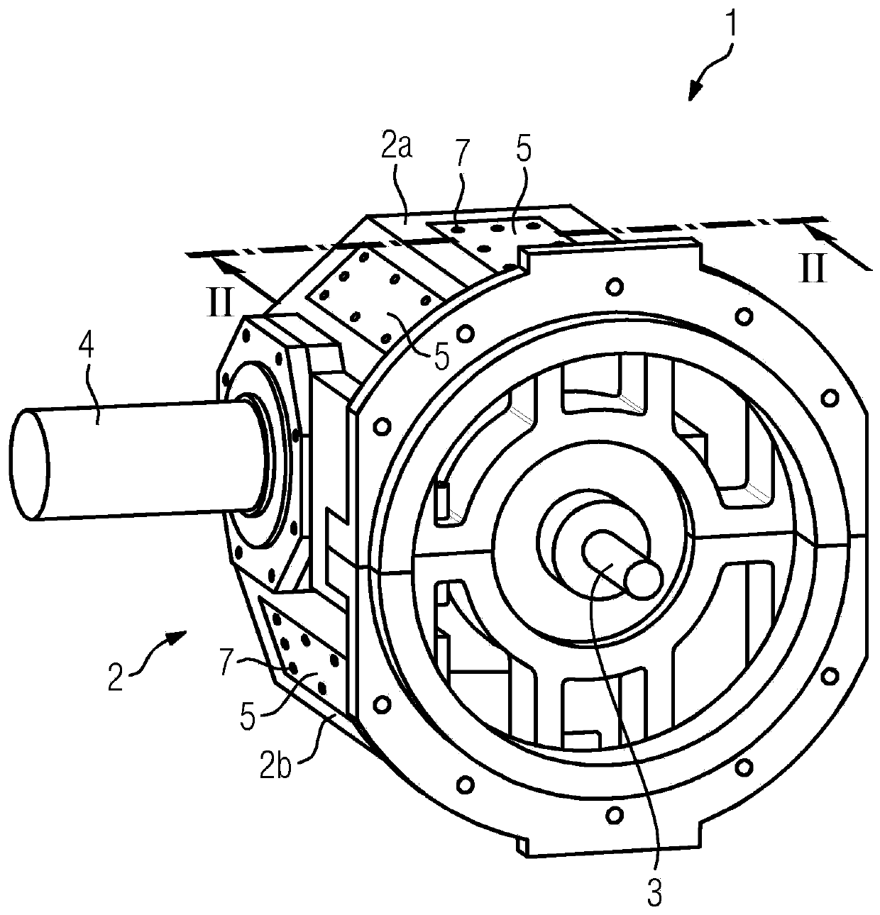
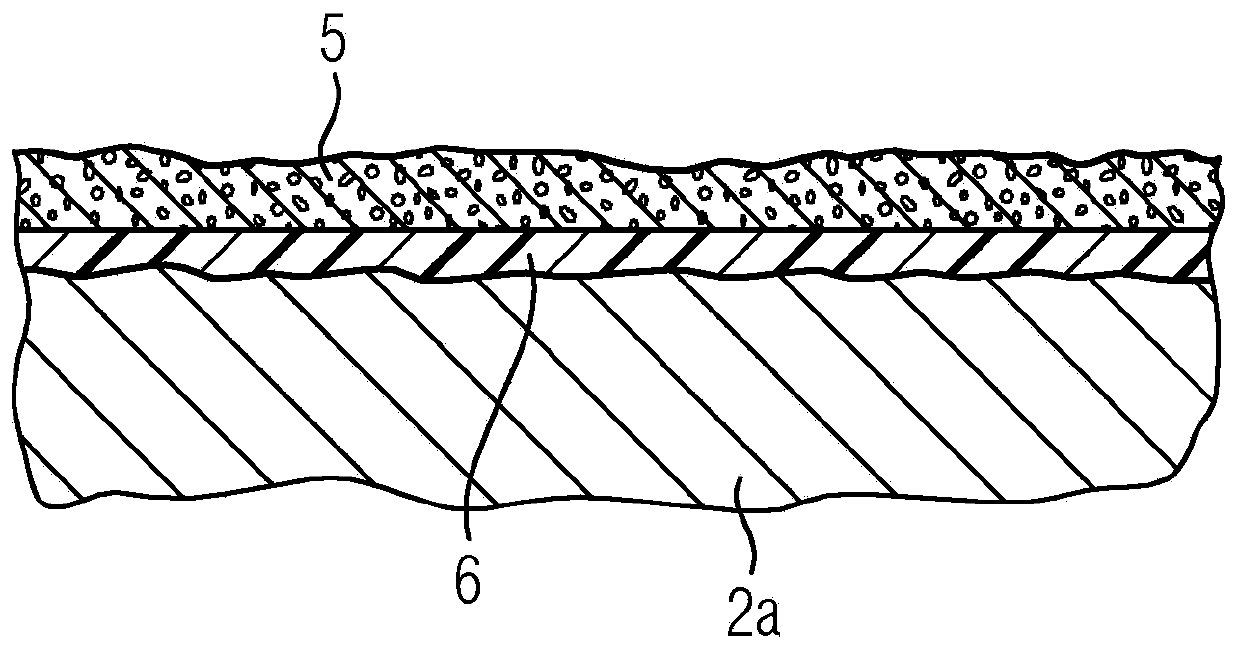
[0016] figure 1 A transmission 1 according to an embodiment of the invention is shown, wherein this is a spur gear designed as a bevel spur gear. Obviously, however, the specific transmission type is not critical to the invention. The transmission 1 has a housing 2 which is divided into an upper housing part 2a and a lower housing part 2b. The upper housing part 2 a and the lower housing part 2 b are here symmetrically constructed and can be cast in the same mold, wherein this is not mandatory. The transmission 1 also comprises a drive shaft 3 and a driven shaft 4 through which the drive power enters the transmission 1 and which is connected to a device not shown, for example a conveyor belt device (for example only). A cooling structure in the form of a cooling element 5 made of open-celled metal foam is arranged on the outer side of the housing 2 , the cooling structure being fastened on the housing 2 as a separate component. The cooling element 5 is currently designed in...
PUM
 Abstract
Description
Claims
Application Information
 - R&D Engineer
- R&D Manager
- IP Professional
- Industry Leading Data Capabilities
- Powerful AI technology
- Patent DNA Extraction
Browse by: Latest US Patents, China's latest patents, Technical Efficacy Thesaurus, Application Domain, Technology Topic, Popular Technical Reports.
© 2024 PatSnap. All rights reserved.Legal|Privacy policy|Modern Slavery Act Transparency Statement|Sitemap|About US| Contact US: help@patsnap.com