
Unmanned aerial vehicle pneumatic auxiliary ejection device

A kind of ejection device and pneumatic auxiliary technology, which is applied in the direction of launch/drag transmission device, etc., can solve the problems of insufficient general launch performance, and achieve the effect of simple structure, fast action speed and strong adaptability

Pending Publication Date: 2020-03-27
BEIJING UNIV OF TECH
View PDF0 Cites 1 Cited by
  • Summary
  • Abstract
  • Description
  • Claims
  • Application Information

AI Technical Summary

Problems solved by technology

Due to the relatively low temperature of gas-steam, simple heat protection device, high energy utilization rate and high structural reliability, but the general emission performance is insufficient

Method used


Image

  • Unmanned aerial vehicle pneumatic auxiliary ejection device
  • Unmanned aerial vehicle pneumatic auxiliary ejection device
  • Unmanned aerial vehicle pneumatic auxiliary ejection device

Examples


Embodiment Construction

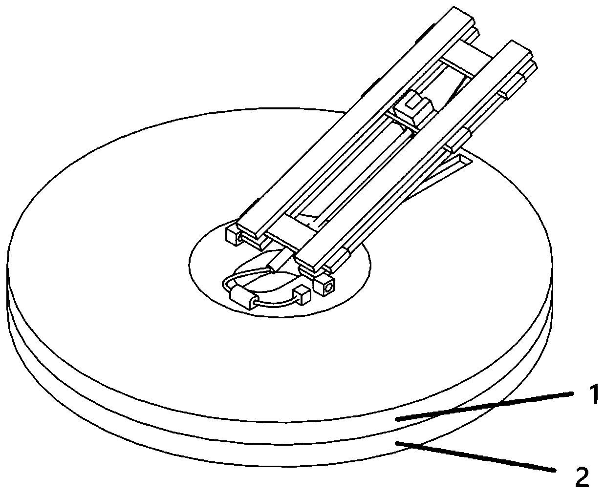
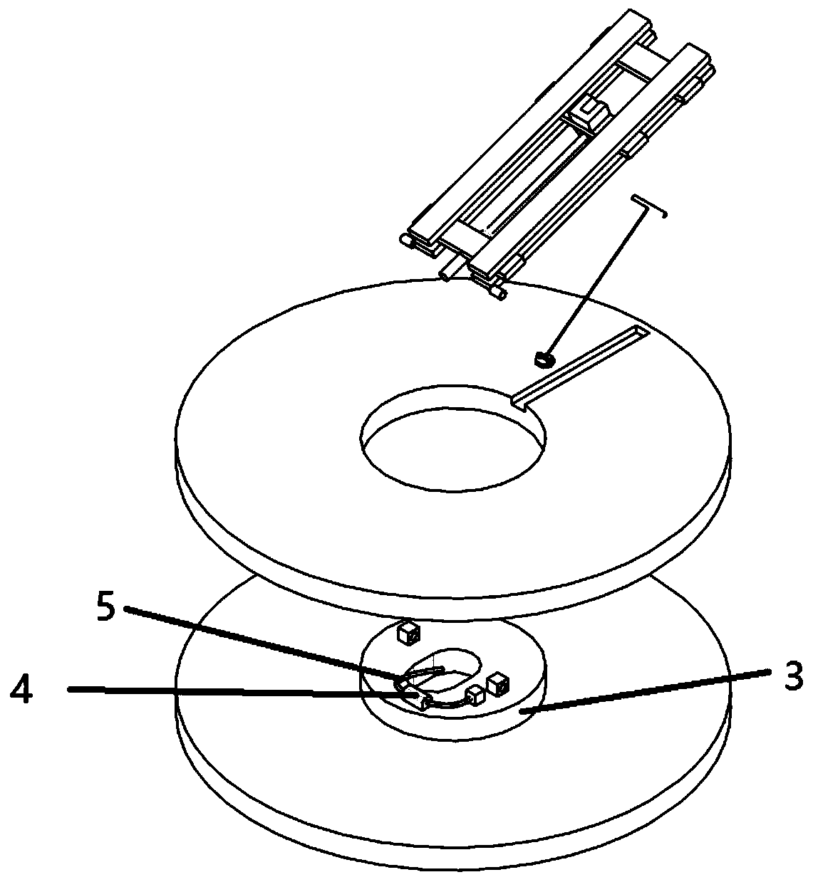
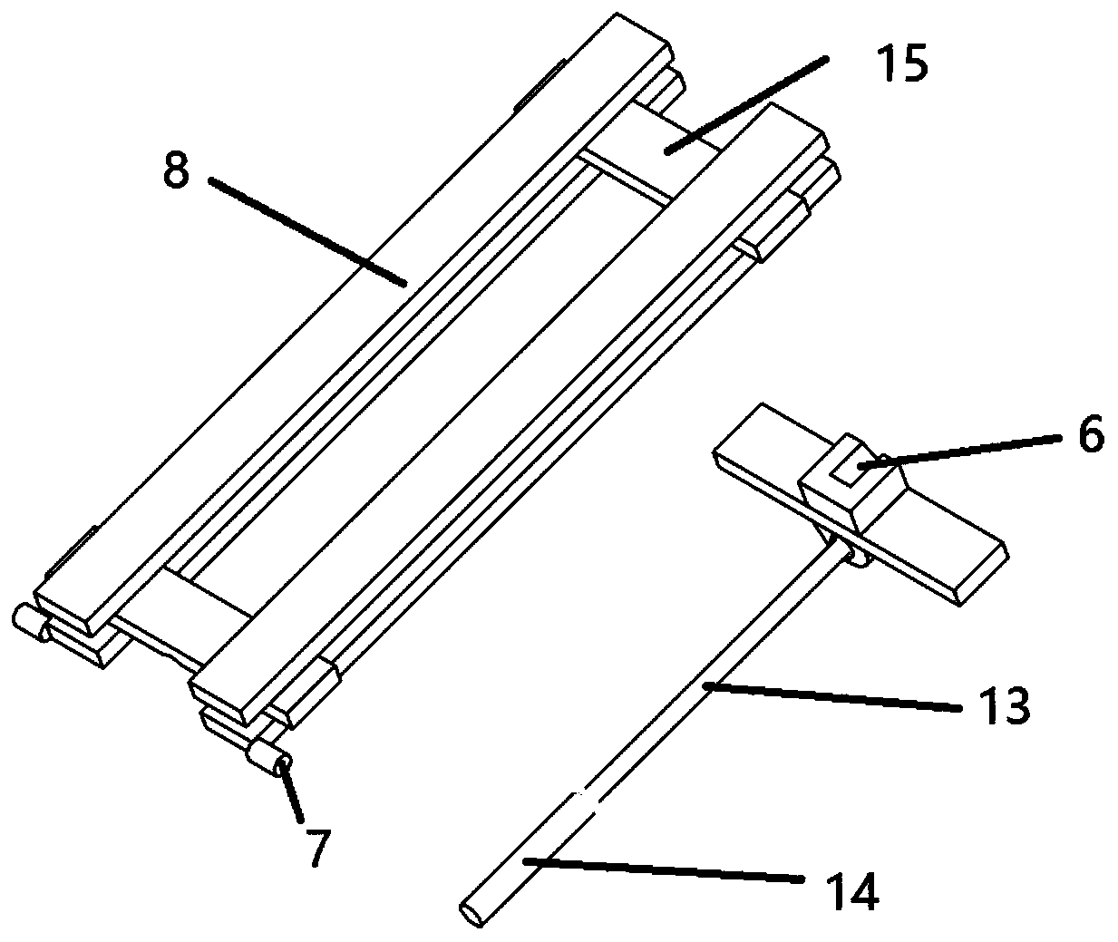
[0023] The whole system is fixed on the ground or other places with stability through the base 2, and the base 1 can be rotated to achieve the desired launching azimuth. When it needs to be used, place the object that needs to be ejected on the stage 6 . Utilize the launch height adjustment lever 11 to adjust the initial launch angle of the ejected object. After the initial azimuth angle and the initial launch angle are determined, a certain amount of gas is collected by the gas collecting device 12 to the high-pressure air pump 4, and the gas required for ejection is compressed by the high-pressure air pump, and the high-pressure gas is transmitted to the high-pressure air chamber 14 through the ventilation pipe 5, and then When the high-pressure gas will push the ejection rod 13 to move towards the ejection baffle 15, the stage will stop moving after touching the ejection baffle 15, but the ejected objects placed on the stage 6 will move at a certain initial velocity under t...


PUM


Abstract

The invention discloses a pneumatic auxiliary ejection device for an unmanned aerial vehicle. The pneumatic auxiliary ejection device comprises a base, a base, a fixed base connector, a high-pressureair pump, an air duct, an objective table, a connecting structure, an ejection height adjusting rod, a rotating rod, an ejection height adjusting rod fixing disc and the like. The system utilizes thelaunching height adjusting rod to adjust the initial launching angle of the launched object. Determining an initial azimuth angle and an initial emission angle; the gas collecting device collects a certain amount of gas to the high-pressure gas pump; gas needed by ejection is compressed through the high-pressure gas pump, the high-pressure gas is transmitted to the high-pressure gas chamber through the ventilation pipeline, at the moment, the high-pressure gas pushes the ejection rod to move towards the ejection baffle, the objective table stops moving after making contact with the ejection baffle, and an ejection object placed on the objective table flies out at a certain initial speed under the action of inertia. The related device designed by the invention has a related structure for adjusting the orientation, and can be adjusted to the required emission orientation in a short time.

Description

technical field [0001] The invention relates to a pneumatic ejection device, which is mainly used for auxiliary launching of unmanned aerial vehicles and the like, and belongs to the technical field of unmanned aerial vehicle design. Background technique [0002] A catapult is a device that applies a corresponding initial velocity to the projected object by relying on its own power or external power. It is mainly used for launching rockets, missiles, and drones. With the rapid development of ejection technology, ejection devices are also showing a trend of diversification. According to the classification of launch power, they are mainly divided into cold launch and hot launch. [0003] Cold launch is a launch method in which the projectile is ejected by means of external power, and the projectile relies on its own engine to ignite and continue to fly. The former Soviet Union cooperated with the French Thomson-CSF company to realize the cold ejection of the Sidewinder VT-1 m...

Claims


Application Information

Patent Timeline
Patent Type & Authority Applications(China)
IPC IPC(8): B64F1/06
CPCB64F1/06
Inventor 赵旭程维虎姬庆庆闫清萱孟佳晖关棋月魏少杰陈楠胡羽彤龚煜涵
Owner BEIJING UNIV OF TECH
Learn More