
Unmanned aerial vehicle camera shooting aerial photography suspension holder

A drone and aerial photography technology, applied in the field of drones, can solve problems such as camera damage, drone drop, drone not mentioned, etc., to achieve the effect of ensuring efficiency and ensuring cleanliness

Active Publication Date: 2020-03-27
NANJING FORESTRY UNIV
View PDF6 Cites 10 Cited by
  • Summary
  • Abstract
  • Description
  • Claims
  • Application Information

AI Technical Summary

Problems solved by technology

[0003] However, the following problems exist in the use of UAVs in the process of taking pictures. a. When the UAV is taking pictures outdoors, the surface of the camera is easy to be covered with dust, especially in harsh rainy and snowy weather. The covered snowflakes cannot be processed in time, and need to be cleared manually after landing the drone, which affects the efficiency of the outdoor shooting of the drone. If the drone falls, it is easy to cause damage to the camera installed on the drone, making the camera unusable
[0004] For the technical problems existing in the current use of drones in camera use, personnel in related technical fields have made adaptation improvements after research, such as the Chinese invention patent lightweight drone platform with patent number 201811161972.3, which can effectively Reduce the size of the gimbal, making the gimbal of the UAV lighter and more portable. However, the above-mentioned problems in the use of the UAV in the process of taking pictures are not mentioned.

Method used


Image

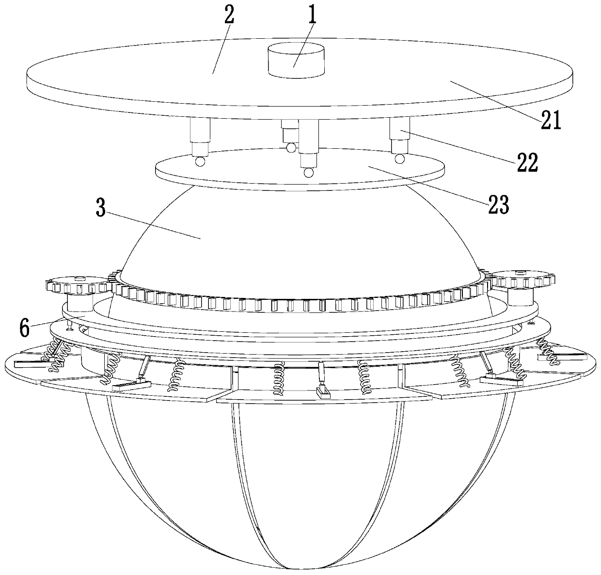
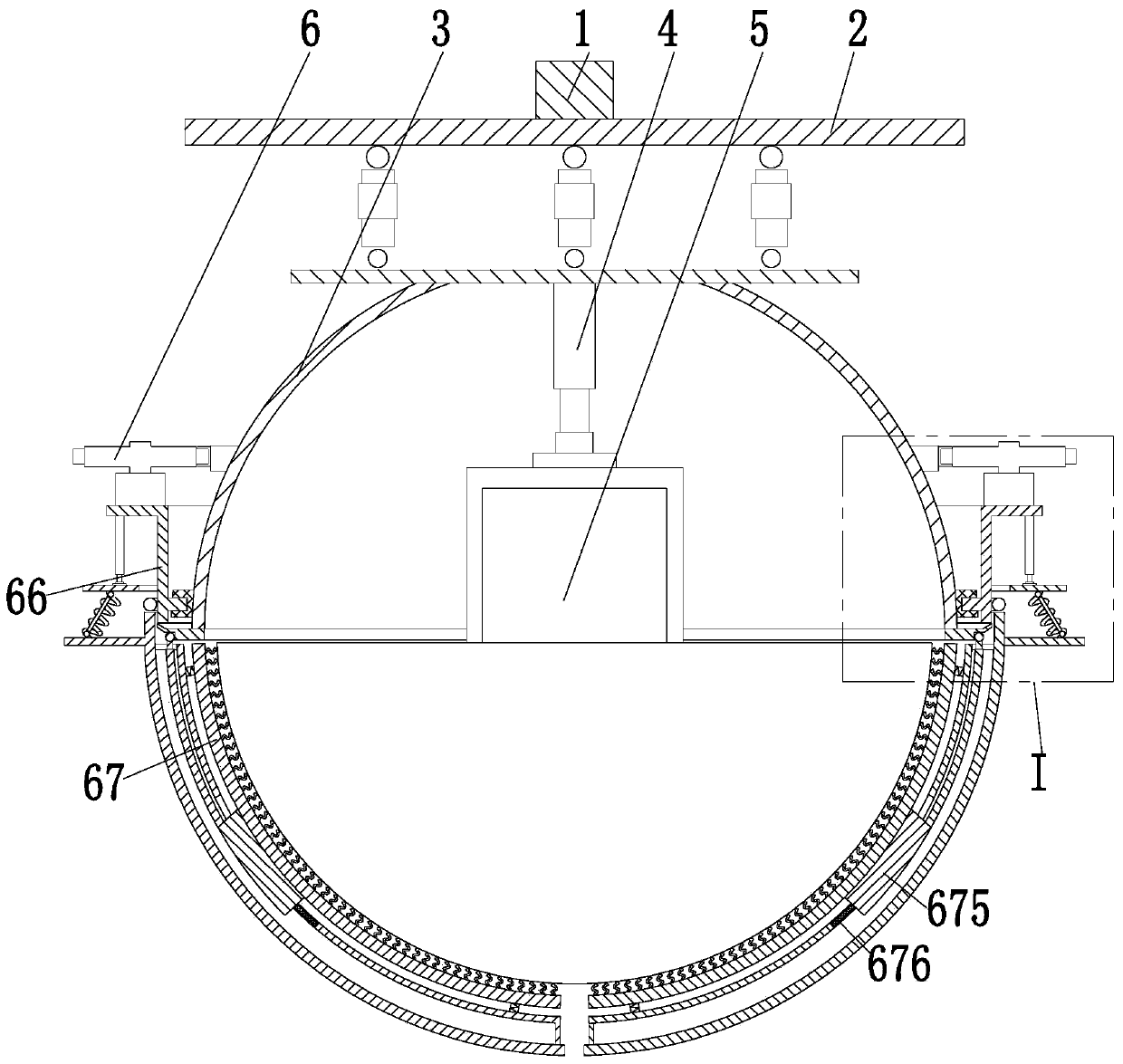
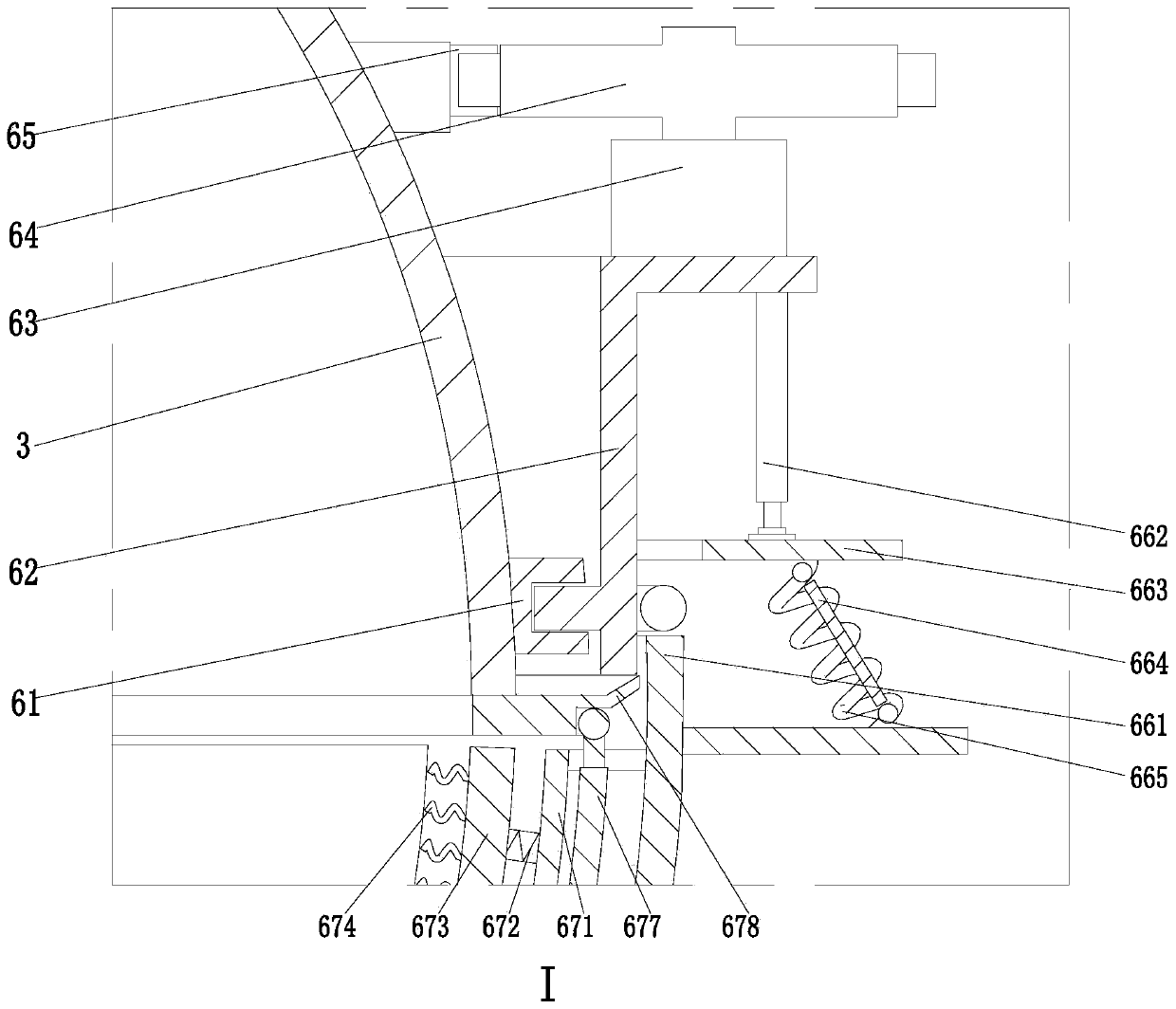
  • Unmanned aerial vehicle camera shooting aerial photography suspension holder
  • Unmanned aerial vehicle camera shooting aerial photography suspension holder
  • Unmanned aerial vehicle camera shooting aerial photography suspension holder

Examples


Embodiment Construction

[0021] The embodiments of the present invention will be described in detail below with reference to the accompanying drawings, but the present invention can be implemented in many different ways defined and covered by the claims.

[0022] Such as Figure 1 to Figure 4 As shown, a kind of unmanned aerial vehicle camera suspension cloud platform includes installation block 1, and the lower end of installation block 1 is equipped with steering mechanism 2, and the lower end of steering mechanism 2 is installed with protective bracket 3, and protective bracket 3 is hemispherical structure A telescopic electric push rod 4 is installed on the inner wall of the protective bracket 3, a spherical camera 5 is installed at the lower end of the telescopic electric push rod 4, and a cleaning protection mechanism 6 is arranged on the outer wall of the protective bracket 3;

[0023] The direction adjustment mechanism 2 can control the protective bracket 3 to perform angle adjustment operatio...


PUM


Abstract

The invention relates to an unmanned aerial vehicle camera shooting aerial photography suspension holder. The device comprises a installation block, a direction adjusting mechanism is mounted at the lower end of the installation block, a protective support is mounted at the lower end of the direction adjusting mechanism, a telescopic electric push rod is mounted on the inner wall of the protectivesupport, a spherical camera is mounted at the lower end of the telescopic electric push rod, and a cleaning protective mechanism is arranged on the outer wall of the protective support. According tothe invention, the following problems of an existing unmanned aerial vehicle in a shooting use process can be solved; when the unmanned aerial vehicle carries out photographing operation outdoors, thesurface of a camera is easily covered with dust; especially in rainy and snowy weather with severe environment, the environment is protected; b, water mist or covered snowflakes on the surface of thecamera cannot be treated in time, the unmanned aerial vehicle is prone to falling off due to accidents when shooting and framing are conducted outside under the condition of severe weather, the camera installed on the unmanned aerial vehicle is prone to being damaged, and the camera cannot be used.

Description

technical field [0001] The invention relates to the technical field of unmanned aerial vehicles, in particular to a suspended platform for aerial photography of unmanned aerial vehicles. Background technique [0002] Unmanned aircraft, referred to as "UAV", is an unmanned aircraft controlled by radio remote control equipment and its own program control device. With the continuous maturity of UAV technology, UAVs are widely used in various fields. Especially after the development and maturity of the technology that drones can carry camera equipment for shooting when flying in the air, people use the technology of drone shooting for surveying and mapping, monitoring, management and inspection. When drones carry camera equipment to work, they need to pass The cloud platform is installed and connected, and the cloud platform with a suspension structure is one of them. [0003] However, the following problems exist in the use of UAVs in the process of taking pictures. a. When th...

Claims


Application Information

Patent Timeline
IPC IPC(8): B64D47/08B64F5/30B08B1/04B08B1/00
CPCB64D47/08B64F5/30B08B1/143B08B1/32
Inventor 张宁
Owner NANJING FORESTRY UNIV
Learn More