Eureka AIR delivers breakthrough ideas for toughest innovation challenges, trusted by R&D personnel around the world.

Base with massage function for new energy vehicle

A new energy vehicle and seat technology, applied in vehicle seats, massage accessories, pneumatic massage, etc., can solve problems such as unreasonable, short cruising range, etc., and achieve the effect of increasing massage force and better massage effect

Inactive Publication Date: 2020-03-27
朱育明
View PDF0 Cites 6 Cited by
  • Summary
  • Abstract
  • Description
  • Claims
  • Application Information

AI Technical Summary

Problems solved by technology

However, since new energy vehicles have the problem of short cruising range, it is unreasonable to use electric drive to add massage function to car seats

Method used


Image

  • Base with massage function for new energy vehicle
  • Base with massage function for new energy vehicle
  • Base with massage function for new energy vehicle

Examples


Embodiment 1

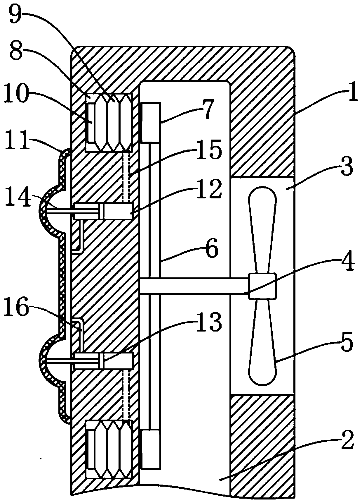
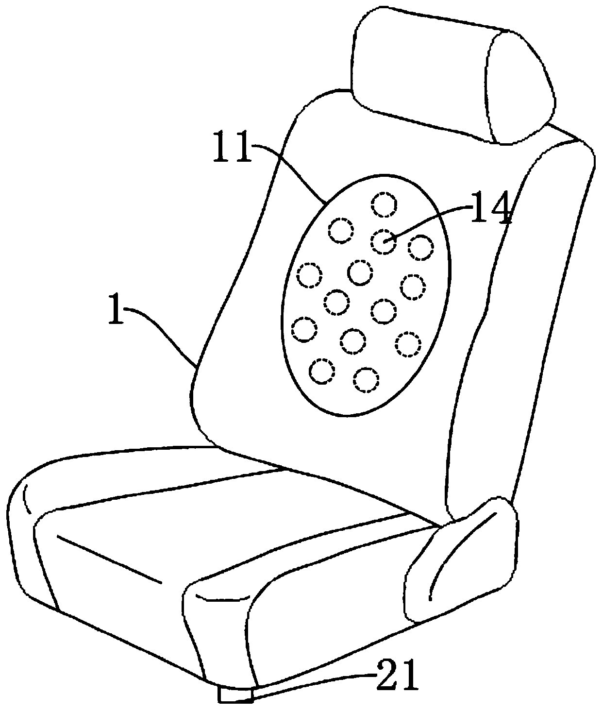
[0020] refer to Figure 1-2 , a seat with a massage function for a new energy vehicle, comprising a seat body 1, a cavity 2 is provided in the seat body 1, and an air inlet 21 connecting the exterior of the car and the cavity 2 is provided at the lower end of the seat body 1 Specifically, the air inlet 21 communicates with the air intake channel at the center grille of the front face of the car through the air intake pipe, so as to ensure that the air inlet 21 has sufficient air volume input during the running of the car, and the side wall on the back of the seat body 1 There is an air outlet 3 connected to the cavity 2, and the air outlet 3 is connected to the heat dissipation system of the automobile. The airflow entering the cavity 2 will eventually flow to the heat dissipation system of the automobile through the air outlet 3 to assist the heat dissipation of the automobile.

[0021] A rotating shaft 4 is rotatably connected to the inner wall of the cavity 2 , and the rota...

Embodiment 2

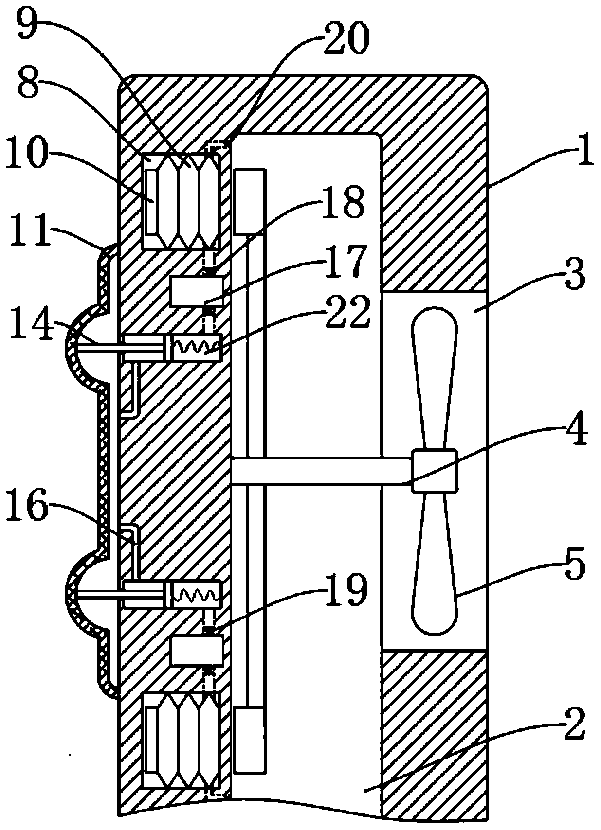
[0030] refer to image 3 , and the difference from Embodiment 1 is that: the air delivery chamber 15 is communicated with a pressure chamber 17, and the input end of the air delivery chamber 15 is equipped with a first one-way valve 18 that only allows air to flow from the telescopic air bag 9 to the pressure chamber 17, and the input end of the air delivery chamber 15 is installed The output end of the air chamber 15 is equipped with a valve group 19 that only allows air to flow from the pressure chamber 17 to the slide chamber 12 .

[0031] It should be noted that the valve group 19 includes a one-way valve and a pressure valve, and the critical value of the pressure valve is relatively high, about three to four atmospheres, so only when the air pressure in the pressure chamber 17 reaches a certain value , the pressure valve will open, and the airflow will flow into the sliding chamber 12 with a relatively high explosive force.

[0032] The telescopic airbag 9 is provided wit...


PUM


Abstract

The invention discloses a base with a massage function for a new energy vehicle. The vehicle base comprises a base body, a cavity is formed in the base body, an air inlet communicated with the exterior of an vehicle and the cavity is formed in the lower end of the base body, an air outlet communicated with the cavity is formed in the side wall of the back face of the base body, a rotating shaft isrotationally connected to the inner side wall of the cavity, and the rotating shaft extends into the air outlet. An impeller, a permanent magnet block, a permanent magnet sheet, a telescopic air bag,a sliding rod, a massage back cushion and a pressure cavity are arranged; the invention discloses a new energy vehicle driving method. All the telescopic air bags convey air to the sliding cavities communicated with the telescopic air bags in sequence; the pressure cavity can store gas output by the telescopic air bag, and the gas is released when the air pressure reaches a certain value, so thatthe sliding rods slide with greater force, the massage force of the massage back cushion is increased, and the massage effect of the base is better.

Description

technical field [0001] The invention relates to the field of new energy technologies, in particular to a seat with a massage function for a new energy vehicle. Background technique [0002] With the increasing shortage of traditional energy sources, new energy vehicles have emerged at the historic moment. New energy vehicles have the advantages of environmental protection and energy saving, and usually enjoy certain subsidies when purchasing, so they have gradually become a major market share in the automotive market. . [0003] Due to the limitation of battery capacity, new energy vehicles are generally not equipped with seats with massage function. For urban white-collar workers, after a busy day at work, the process of driving home is very tiring. The state is not good, and the traffic conditions in the urban area are complicated, which is prone to danger. If the car seat has a massage function at this time, it can help the driver dispel fatigue and improve the driver's ...

Claims


Application Information

Patent Timeline
Patent Type & Authority Applications(China)
IPC IPC(8): B60N2/90B60N2/56A61H9/00A61N2/08
CPCA61H9/0078A61H2201/0149A61N2/002A61N2/06B60N2/5657B60N2/976
Inventor 朱育明
Owner 朱育明
Why Eureka
Eureka Blog
Learn More