Space-saving placing rack for medical equipment

A medical equipment and space-saving technology, applied in the field of placement racks, can solve problems such as free adjustment of placement racks, and achieve the effect of improving space utilization.

Pending Publication Date: 2020-03-27
陕西鑫威泰生物科技有限公司
View PDF0 Cites 0 Cited by
  • Summary
  • Abstract
  • Description
  • Claims
  • Application Information

AI Technical Summary

Problems solved by technology

[0004] The purpose of the present invention is to solve the problem that the internal structure of the placement rack is relatively simple in the prior art, and the placement rack cannot be adjusted freely according to the size of the equipment, and a space-saving medical equipment placement rack is proposed.

Method used


Image

  • Space-saving placing rack for medical equipment
  • Space-saving placing rack for medical equipment

Examples


Embodiment Construction

[0019] The following will clearly and completely describe the technical solutions in the embodiments of the present invention with reference to the accompanying drawings in the embodiments of the present invention. Obviously, the described embodiments are only some, not all, embodiments of the present invention.

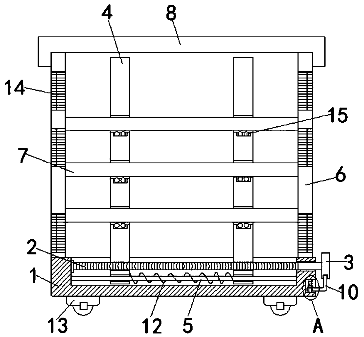
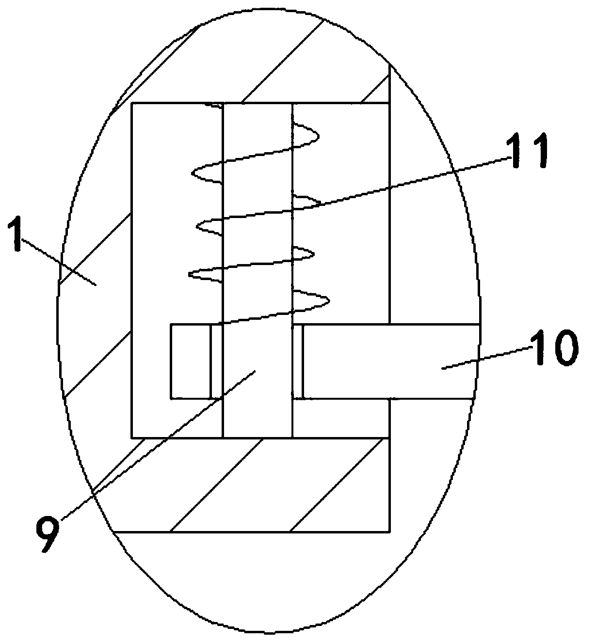
[0020] refer to Figure 1-2 , a space-saving medical device placement rack, including a base 1, a chute is provided on the top of the base 1, and a connecting screw 2 is rotated in the chute to drive the baffle 4 to move, and one end of the screw 2 runs through the inner wall of the chute and A knob 3 is fixedly connected to drive the screw 2 to rotate. One end of the screw 2 located in the chute is threaded with two symmetrically arranged baffles 4 for separating the equipment. A slide rod 5 is fixedly connected in the chute. Used to support the baffle 4, the baffle 4 is provided with a through opening corresponding to the slide bar 5, one end of the baffle 4 passes...


PUM


Abstract

The invention discloses a space-saving placing rack for medical equipment. The placing rack includes a base, the top of the base is provided with a slide groove, the interior of the slide groove is rotatably connected with a threaded rod, one end of the threaded rod penetrates the inner wall of the slide groove and is fixedly connected with a rotary knob, and one end, located in the slide groove,of the threaded rod is in threaded sleeve connection with two symmetrically arranged baffles; a slide rod is fixedly connected in the slide groove, each baffle is provided with a pass-through openingcorresponding to the slide rod, and one end of each baffle penetrates an opening of the slide groove and extends upwards; and the top of the base is fixedly connected with a main frame, the baffles are slidably provided with a plurality of horizontally arranged placing plates in an insertion manner, and two ends of each placing plate are fixedly connected to the inner walls of two sides of the main frame. Through the adjustable baffles, when the device can place the equipment, the device can be correspondingly adjusted according to actual conditions, so that the space utilization rate of the placing rack is improved.

Description

technical field [0001] The invention relates to the technical field of placing racks, in particular to a space-saving medical equipment placing rack. Background technique [0002] Most of the patients in the hospital need clinical care. Often the medical personnel hold the trays containing the medical equipment with their hands and monitor the patients in the ward. Because they need to check the patient's condition, they have to take out the equipment in the shelf for use. Treat the sick. [0003] However, the internal structure of the existing rack is relatively simple, and the rack cannot be adjusted freely according to the size of the equipment, thereby affecting the space utilization rate of the rack. Contents of the invention [0004] The object of the present invention is to solve the problem that the internal structure of the shelf is relatively simple in the prior art, and the shelf cannot be freely adjusted according to the size of the equipment, and proposes a s...

Claims


Application Information

Patent Timeline
Patent Type & Authority Applications(China)
IPC IPC(8): A61B50/22
CPCA61B50/22
Inventor 王鸿才何杰王富民康明锋
Owner 陕西鑫威泰生物科技有限公司
Why Eureka
Try Eureka