Push-close type outgoing line clamp for motor and electric appliance adopting same
A technology of outlet clips and outlet ends, which is applied in the field of push-fit outlet clips for motors and electrical appliances using them. It can solve problems such as misalignment and offset of power lead wires, and achieve the advantages of avoiding offset and misalignment, easy disassembly, and good protection. Effect
- Summary
- Abstract
- Description
- Claims
- Application Information
AI Technical Summary
Problems solved by technology
Method used
Image
Examples
Embodiment 1
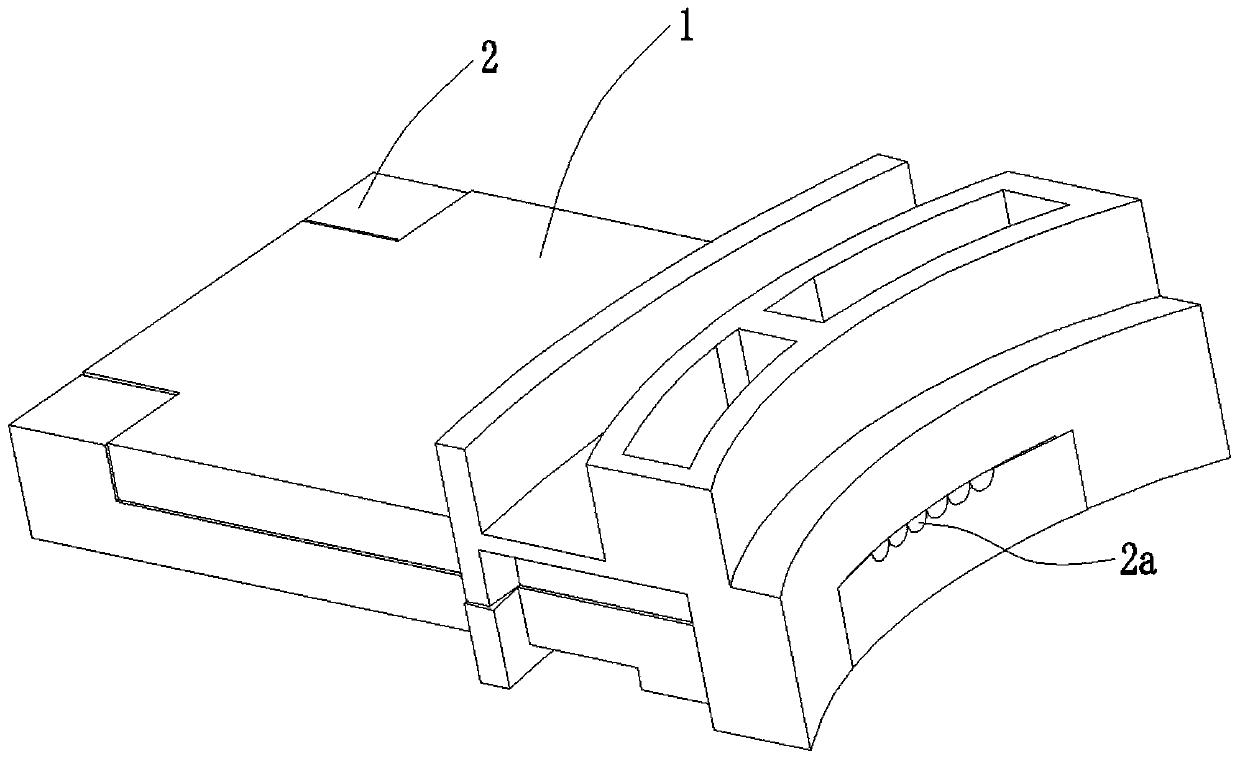
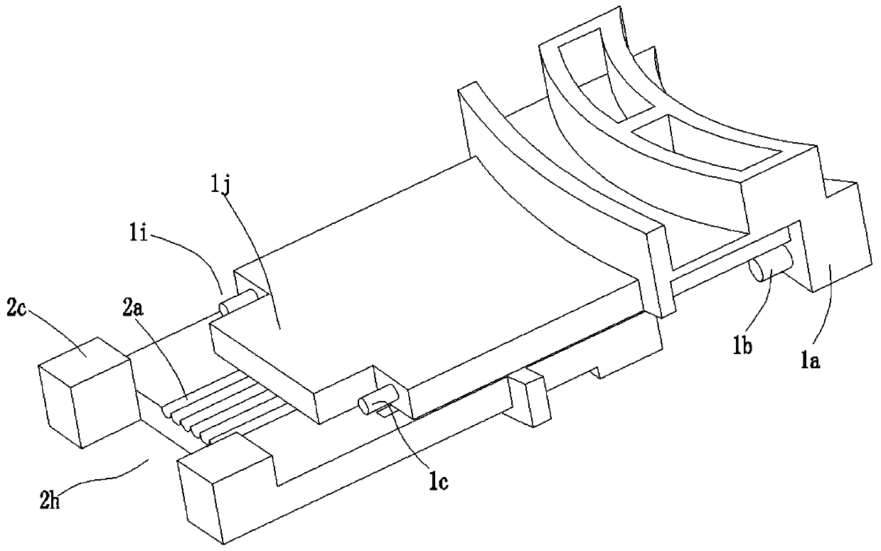
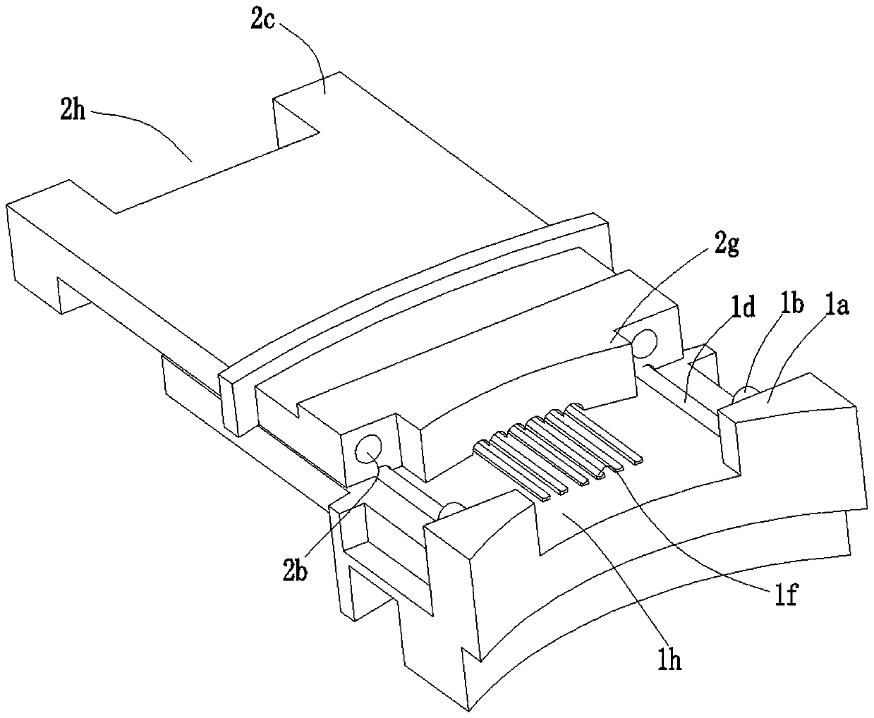
[0045] A push-fit type outlet clip for motors, which is used to solve the existing wire outlet clips that easily lead to power line offset, misalignment, difficulty in disassembly, and high scrap rate, and can effectively fix the power lead-out wire to ensure the reliability of the power lead-out wire The long-term use safety of the motor can also reduce the disassembly and scrap rate, and realize the recycling and reuse of the outlet clips, such as figure 1 , figure 2 , image 3 , Figure 4 , Figure 5 As shown, specifically set to the following structure:
[0046] In this embodiment, the push-fit outlet clip includes an upper clip 1 and a lower clip 2 made of PA66 high-temperature-resistant material, which better solves the defects of the original outlet clip end upturned and the gap between the upper and lower outlet clips is large .
[0047] The working surface of the lower clip 2 of the push-fit type outlet clamp has wire slots 2a. Generally speaking, the wire slots...
Embodiment 2
[0054] This embodiment is further optimized on the basis of the above-mentioned embodiments, further to better realize the present invention, especially adopt the following configuration structure:
[0055] Between the lower clamp 2 and the upper clamp 1, there is a guide structure that cooperates with each other. The guide structure is used to keep the upper clamp 1 to move along the axial direction of the wire groove 2a, and to keep the upper clamp 1 to move along the axial direction of the wire groove 2a, which is convenient The assembly alignment of the upper clamp 1 and the lower clamp 2 improves assembly efficiency.
[0056] Specifically, the guide structure includes a paired guide slideway 2e and a guide slide protrusion 1d, the guide slideway 2e is arranged on the working surface of the lower clamping plate of the lower clamp 2, and the direction of the guide slideway 2e is parallel to the axial direction of the wire groove 2a ; The guide slideway 2e is set on the work...
Embodiment 3
[0060] This embodiment is further optimized on the basis of the above-mentioned embodiments, further to better realize the present invention, especially adopt the following configuration structure:
[0061] In order to increase the pressing force on the power lead-out wires, the working surface of the upper clamping plate of the upper clip 1 is provided with convex ribs 1e for pressing the power lead-out wires. Generally, there are multiple rows of convex ribs 1e. The direction is parallel to the axial direction of the wire groove 2a, and each wire groove 2a is paired with one of the convex ribs 1e, and the convex rib 1e cooperates with the wire groove 2a to effectively fix the power lead-out wires and prevent the power lead-out wires from shifting and dislocation .
[0062] In order to be able to compress the power lead-out wires more effectively, an effective way is to increase the pressing surface between the convex rib 1e and the power lead-out wire. Therefore, a concave a...
PUM
 Abstract
Description
Claims
Application Information
 - R&D
- Intellectual Property
- Life Sciences
- Materials
- Tech Scout
- Unparalleled Data Quality
- Higher Quality Content
- 60% Fewer Hallucinations
Browse by: Latest US Patents, China's latest patents, Technical Efficacy Thesaurus, Application Domain, Technology Topic, Popular Technical Reports.
© 2025 PatSnap. All rights reserved.Legal|Privacy policy|Modern Slavery Act Transparency Statement|Sitemap|About US| Contact US: help@patsnap.com


