Cylindrical shell modal vibration sound radiation testing device based on laser scanning

A technology of laser scanning and testing equipment, which is applied in vibration testing, measuring equipment, testing of machines/structural components, etc., and can solve problems such as low testing accuracy

Inactive Publication Date: 2020-03-24
BEIFANG UNIV OF NATITIES
View PDF4 Cites 1 Cited by
  • Summary
  • Abstract
  • Description
  • Claims
  • Application Information

AI Technical Summary

Problems solved by technology

[0002] Cylindrical shells are typical engineering structural parts, widely used in aviation, aerospace and other general mechanical equipment, such as casings of aero-engines, various cabins of spacecraft, and drums in granulators, to obtain the modal of cylindrical shells The mode shape is of great significance to the dynamic design and vibration suppression of this type of structural parts. For a long time, the test of the mode shape of the cylindrical shell mainly adopts the method provided by the general experimental modal analysis theory, that is, by testing each response The frequency response function of the point is used to identify the mode shape. The most common method is to use a hammer or an electromagnetic exciter to stimulate the test. This traditional method of testing the mode shape is not very accurate. Therefore, we A laser-scanning modal vibration-acoustic radiation testing device for cylindrical shells is proposed

Method used


Image

  • Cylindrical shell modal vibration sound radiation testing device based on laser scanning
  • Cylindrical shell modal vibration sound radiation testing device based on laser scanning

Examples


Embodiment Construction

[0015] In order to make the technical means, creative features, objectives and effects of the present invention easy to understand, the present invention will be further explained below in conjunction with specific embodiments.

[0016] In the description of the present invention, it should be noted that the terms "upper", "lower", "inner", "outer", "front end", "rear end", "two ends", "one end", "the other end" The orientation or positional relationship of other indications is based on the orientation or positional relationship shown in the drawings, which is only used to facilitate the description of the present invention and simplify the description, and does not indicate or imply that the device or element referred to must have a specific orientation and a specific orientation. The azimuth structure and operation cannot be understood as a limitation of the present invention. In addition, the terms "first" and "second" are only used for descriptive purposes, and cannot be unde...


PUM


Abstract

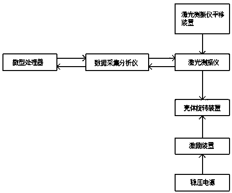
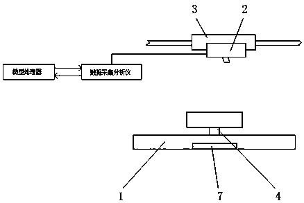
The invention discloses a cylindrical shell modal vibration sound radiation testing device based on laser scanning, relates to the field of cylindrical shell modal vibration acoustic radiation testingdevices. The device comprises an excitation device, a laser vibration meter, a laser vibration meter translation device, a shell rotating device, a data acquisition analyzer, a microprocessor and a stabilized voltage supply, wherein the shell rotating device is located at the upper end of the excitation device, and the laser vibration meter is located above the shell rotating device. Characteristic parameters such as modal shape, inherent frequency and damping of cylindrical shell vibration under any boundary condition are measured by utilizing test devices such as an excitation device, a laser vibration meter, a laser vibration meter translation device, a shell rotating device, a data acquisition analyzer and a microprocessor; sound pressure (near field or far field) or sound power can be directly measured through experiments, or the sound pressure (near field or far field) or sound power generated by vibration of the cylindrical shell can be indirectly calculated by measuring the vibration speed of the shell, and certain use prospects are achieved.

Description

Technical field [0001] The invention relates to the field of cylindrical shell modal vibration and acoustic radiation testing devices, in particular to a cylindrical shell modal vibration and acoustic radiation testing device based on laser scanning. Background technique [0002] Cylindrical shells are typical engineering structural parts, which are widely used in aviation, aerospace and other general mechanical equipment, such as aircraft engine casings, various cabins of spacecraft, and drums in granulators to obtain the modalities of cylindrical shells The mode shape is of great significance to the dynamic design and vibration suppression of this type of structure. For a long time, the test of the mode shape of the cylindrical shell mainly adopts the method provided by the general experimental modal analysis theory, that is, by testing each response The frequency response function of a point is used to identify the mode shape. Among them, the use of hammer or electromagnetic e...

Claims


Application Information

Patent Timeline
IPC IPC(8): G01M7/02G01H9/00
CPCG01H9/00G01M7/025
Inventor 丁少虎穆春阳高阳李茂强刘宏王富伟
Owner BEIFANG UNIV OF NATITIES
Why Eureka
Try Eureka