Beading finishing equipment for jewelry processing
A technology for stringing beads and accessories, which is applied in the field of beading finishing equipment, can solve the problems of difficulty in fast packaging and cannot be easily collected and arranged for beading, and achieves the effect of reducing the burden
- Summary
- Abstract
- Description
- Claims
- Application Information
AI Technical Summary
Problems solved by technology
Method used
Image
Examples
Embodiment 1
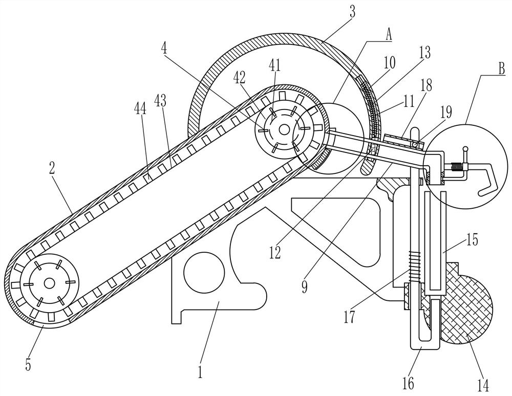
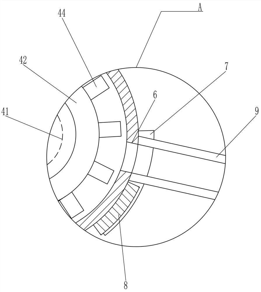
[0019] A kind of beading finishing equipment for jewelry processing, such as Figure 1-2 As shown, it includes a mounting seat 1, a transmission frame 2, an arc-shaped support rod 3, a conveying device 4, a fan-shaped disc 7, an arc-shaped baffle 8, a feeding tube 9, an arc-shaped sliding rod 11, an arc-shaped block 12, a first Compression spring 13, mounting block 14 and collecting frame 15, one side of mounting base 1 is provided with transmission frame 2, and the top of transmission frame 2 is provided with arc support bar 3, and transmission frame 2 is provided with conveying device 4, and transmission frame 2 bottom is opened There is a feed port 5, the upper part of the transmission frame 2 is provided with a discharge port 6, and the upper part of the rear side of the transmission frame 2 is rotatably connected with a fan-shaped disc 7. The fan-shaped disc 7 is provided with an arc-shaped baffle plate 8, and the arc-shaped support rod 3 is opened. There is an arc-shaped...
Embodiment 2
[0023] On the basis of Example 1, such as figure 1 with image 3 As shown, it also includes an L-shaped rod 16, a second compression spring 17, a guide frame 18, a protruding rod 19 and a handle 20, and the mounting base 1 is slidably connected with an L-shaped rod 16, and the L-shaped rod 16 is connected to the mounting base 1 The second compression spring 17 is connected between them, the top of the feed pipe 9 is provided with a guide frame 18, the upper front side of the L-shaped bar 16 is provided with a protruding rod 19, the protruding rod 19 is slidably matched with the guide frame 18, and the right side of the feed pipe 9 is provided with a There are 20 turning handles.
[0024] When the feed pipe 9 rotates counterclockwise, the feed pipe 9 drives the guide frame 18 to rotate counterclockwise. Through the cooperation of the guide frame 18 and the protruding rod 19, the L-shaped rod 16 moves upward, and the second compression spring 17 is stretched, and the L-shaped ...
Embodiment 3
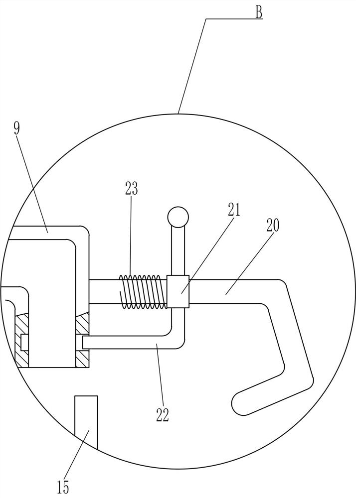
[0026] On the basis of Example 2, such as image 3 As shown, it also includes a sliding push handle 21, a transverse baffle plate 22 and a third compression spring 23, and a sliding push handle 21 is slidably connected to the turning handle 20, and the bottom of the sliding push handle 21 is provided with a transverse baffle plate 22, and the sliding push handle A third compression spring 23 is connected between the handle 21 and the handle 20 .
[0027] When the feeding tube 9 is turned counterclockwise by the handle 20, the sliding push handle 21 and its upper device are pushed to move to the left, and the transverse baffle 22 is snapped into the feeding tube 9, and the third compression spring 23 is compressed, passing through the horizontal baffle. 22. Prevent the beads in the feeding tube 9 from being thrown out during the rotation of the feeding tube 9, which saves the subsequent manual pick-up operation of the worker and achieves the effect of reducing the burden on the...
PUM
 Abstract
Description
Claims
Application Information
 - Generate Ideas
- Intellectual Property
- Life Sciences
- Materials
- Tech Scout
- Unparalleled Data Quality
- Higher Quality Content
- 60% Fewer Hallucinations
Browse by: Latest US Patents, China's latest patents, Technical Efficacy Thesaurus, Application Domain, Technology Topic, Popular Technical Reports.
© 2025 PatSnap. All rights reserved.Legal|Privacy policy|Modern Slavery Act Transparency Statement|Sitemap|About US| Contact US: help@patsnap.com


