
Electric water heater with electric leakage protection function

A leakage protection and electric water heater technology, applied in the direction of fluid heaters, lighting and heating equipment, etc., can solve the problems of waste, inconvenient disassembly, and a large amount of hot water left in the water tank, and achieve the effect of convenient use

Inactive Publication Date: 2020-03-20
盐城市正龙电热科技有限公司
View PDF11 Cites 0 Cited by
  • Summary
  • Abstract
  • Description
  • Claims
  • Application Information

AI Technical Summary

Problems solved by technology

[0004] The purpose of the present invention is to provide an electric water heater with leakage protection function to solve the problem that the existing electric water heaters proposed in the above background technology have a large amount of water to be heated at one time, require a long heating time, and need to wait for a long time before use , it is very inconvenient to use, and the water storage capacity in the water tank is large, and a large amount of hot water is likely to remain in the water tank after use, resulting in waste, and the structure of the existing electric water heater is compact, and the bolts and other parts are installed on the side wall of the tank, so it is not necessary It is easy to disassemble each component for maintenance. The existing electric water heater has a single leakage protection function, which is only for the switch management of the electric water heater's own power supply. If it cannot be turned off, it will guide the current in other circuits, which has certain limitations in use.

Method used


Image

  • Electric water heater with electric leakage protection function
  • Electric water heater with electric leakage protection function
  • Electric water heater with electric leakage protection function

Examples


Embodiment Construction

[0027] The following will clearly and completely describe the technical solutions in the embodiments of the present invention with reference to the accompanying drawings in the embodiments of the present invention. Obviously, the described embodiments are only some, not all, embodiments of the present invention. Based on the embodiments of the present invention, all other embodiments obtained by persons of ordinary skill in the art without making creative efforts belong to the protection scope of the present invention.

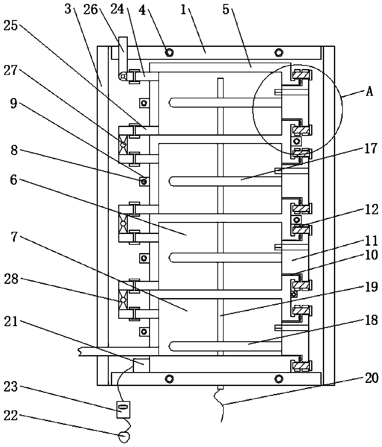
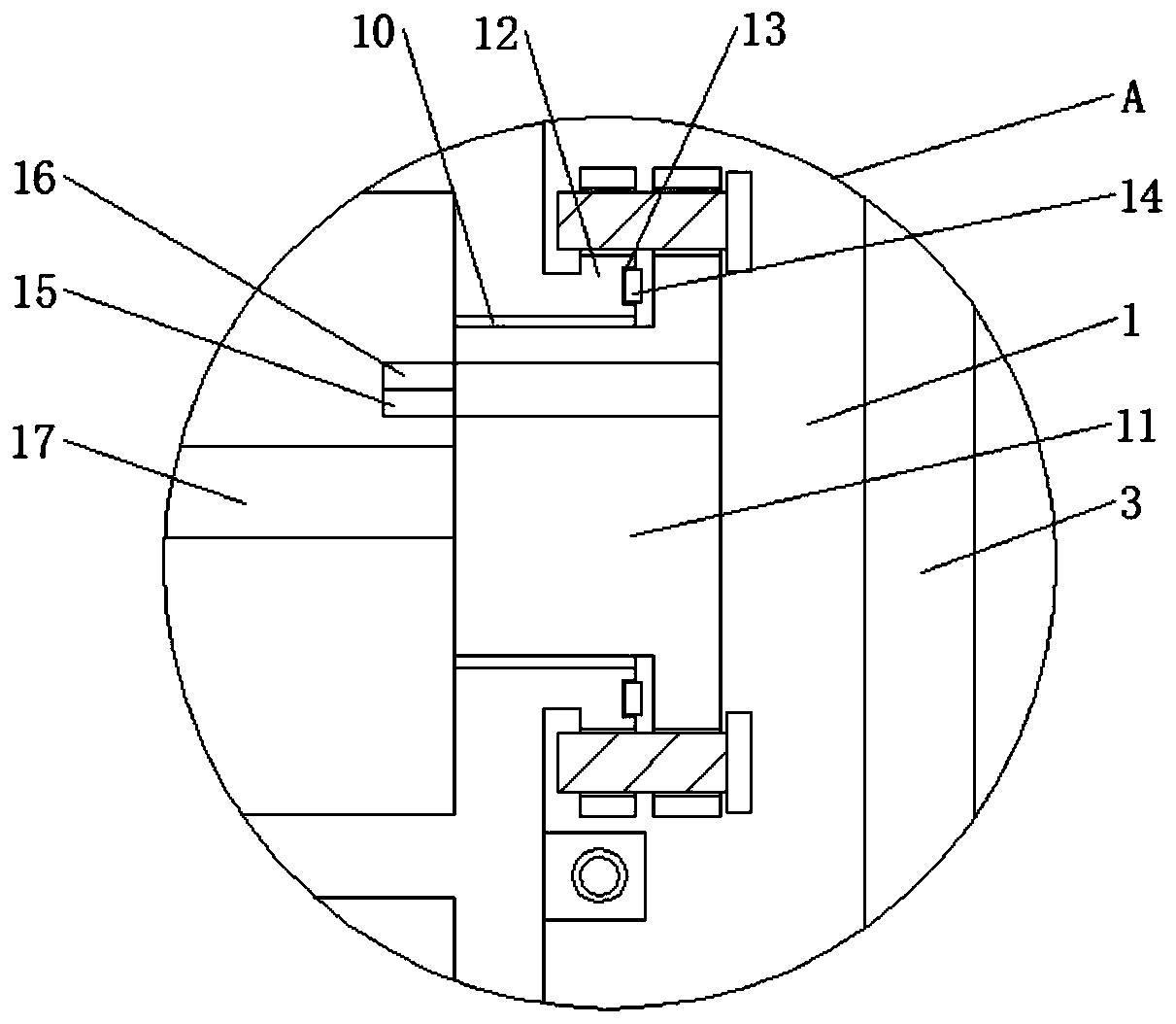
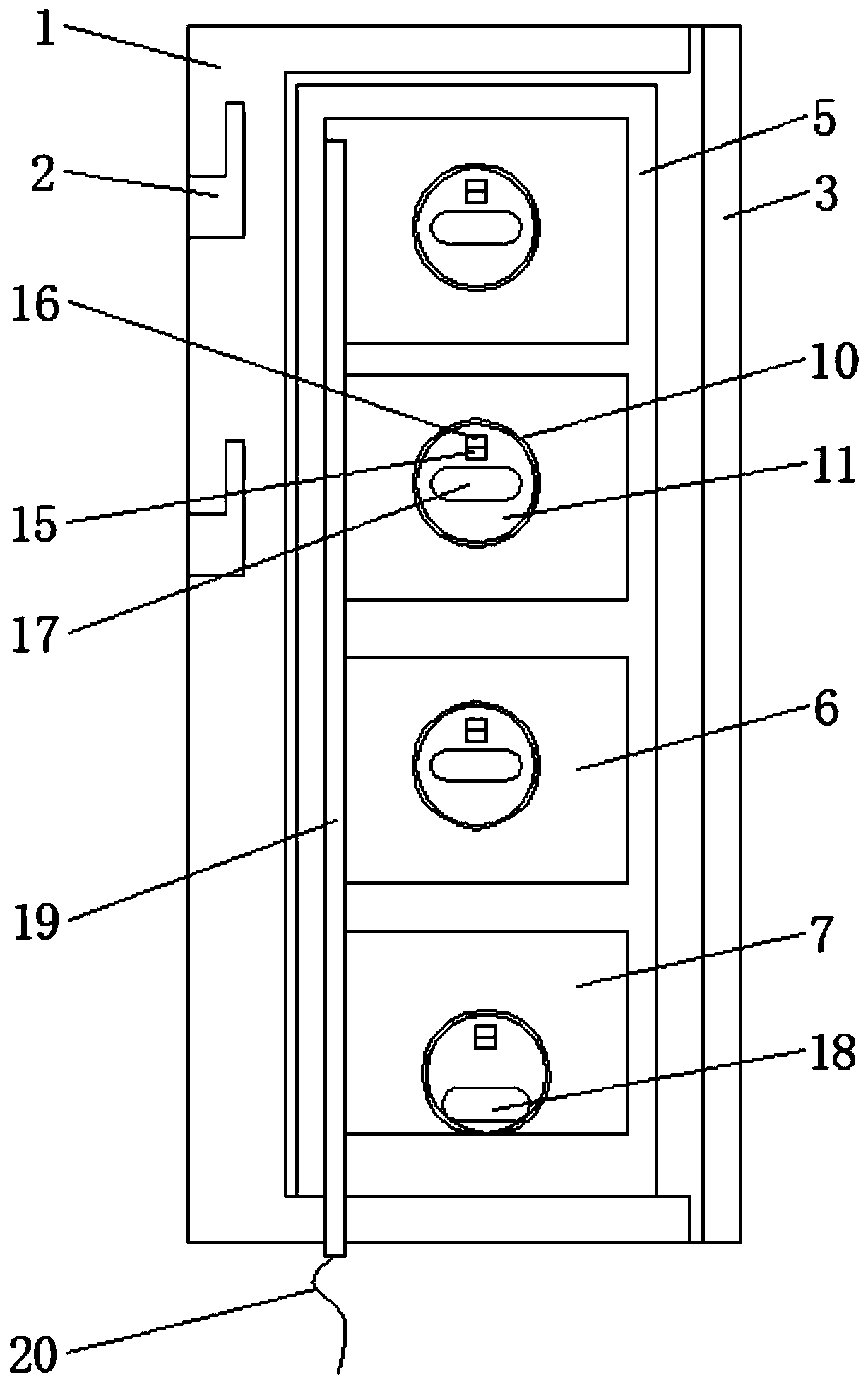
[0028] see Figure 1-6 , the present invention provides a technical solution: an electric water heater with leakage protection function, such as figure 1 , figure 2 and Figure 5 As shown, the rear side of the box body 1 is provided with a hanging groove 2, and the front side of the box body 1 is provided with a box cover 3, the rear end of the box cover 3 and the rear end of the water tank 5 are located on the same vertical plane, and the rear end of the b...


PUM


Abstract

The invention discloses an electric water heater with an electric leakage protection function. The electric water heater comprises a box body, a first bolt and a second bolt; a hanging groove is formed in the rear side of the box body; a box cover is arranged in the front side of the box body; the first bolt penetrates the box cover and is connected with the box body; a water tank is arranged in the box body; a segmented heating chamber and a rapid heating chamber are arranged in the water tank; the rapid heating chamber is arranged under the lowermost segmented heating chamber; the second bolt penetrates through a connecting block and is connected with the box body; the connecting block is arranged in the left side and the right side of the water tank; and openings are formed in the rightside of the segmented heating chamber and the right side of the rapid heating chamber. The electric water heater with the electric leakage protection function is provided with the box cover and the box body, the rearmost ends of the left and right sides of the box cover and the rearmost end of the water tank are located on the same vertical plane, the first bolt is screwed to be taken down, the box cover is separated from the tank body, parts on the left and right sides of the water tank are exposed, parts are convenient to detach for maintenance, and use is more convenient.

Description

technical field [0001] The invention relates to the technical field of electric water heaters, in particular to an electric water heater with an electric leakage protection function. Background technique [0002] An electric water heater refers to a water heating device that uses electricity as an energy source. It is mainly used to heat domestic water and is an indispensable device in family life. [0003] Existing electric water heaters can heat a large amount of water at one time, need to be heated for a long time, and need to wait for a long time before use, which is very inconvenient to use, and the water storage capacity in the water tank is large, and a large amount of hot water is likely to remain in the water tank after use. It causes waste, and the structure of the existing electric water heater is compact, and the parts such as bolts are attached to the side wall of the box, so it is not convenient to disassemble each part for maintenance. The leakage protection f...

Claims


Application Information

Patent Timeline
IPC IPC(8): F24H9/20F24H9/18
CPCF24H9/1818F24H9/2014
Inventor 徐韵粉
Owner 盐城市正龙电热科技有限公司
Learn More