Rotor for a rotary press

A rotary and rotor technology, applied in the direction of presses, material forming presses, manufacturing tools, etc., can solve the problems of product loss, damage efficiency, etc., and achieve the effect of improving efficiency, simple structure, and reducing the surface

Active Publication Date: 2020-03-20
FETTE COMPACTING GMBH
View PDF6 Cites 0 Cited by
  • Summary
  • Abstract
  • Description
  • Claims
  • Application Information

AI Technical Summary

Problems solved by technology

On the one hand, this impairs efficiency and, on the other hand, leads to undesired product losses in the area of ​​the die plate

Method used


Image

  • Rotor for a rotary press
  • Rotor for a rotary press
  • Rotor for a rotary press

Examples


Embodiment Construction

[0024] Unless otherwise stated, the same reference numerals in the figures denote the same objects.

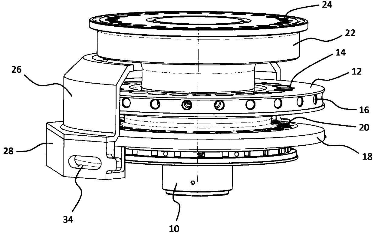
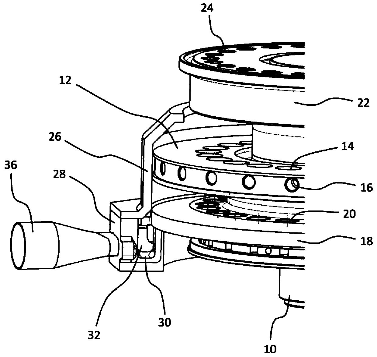
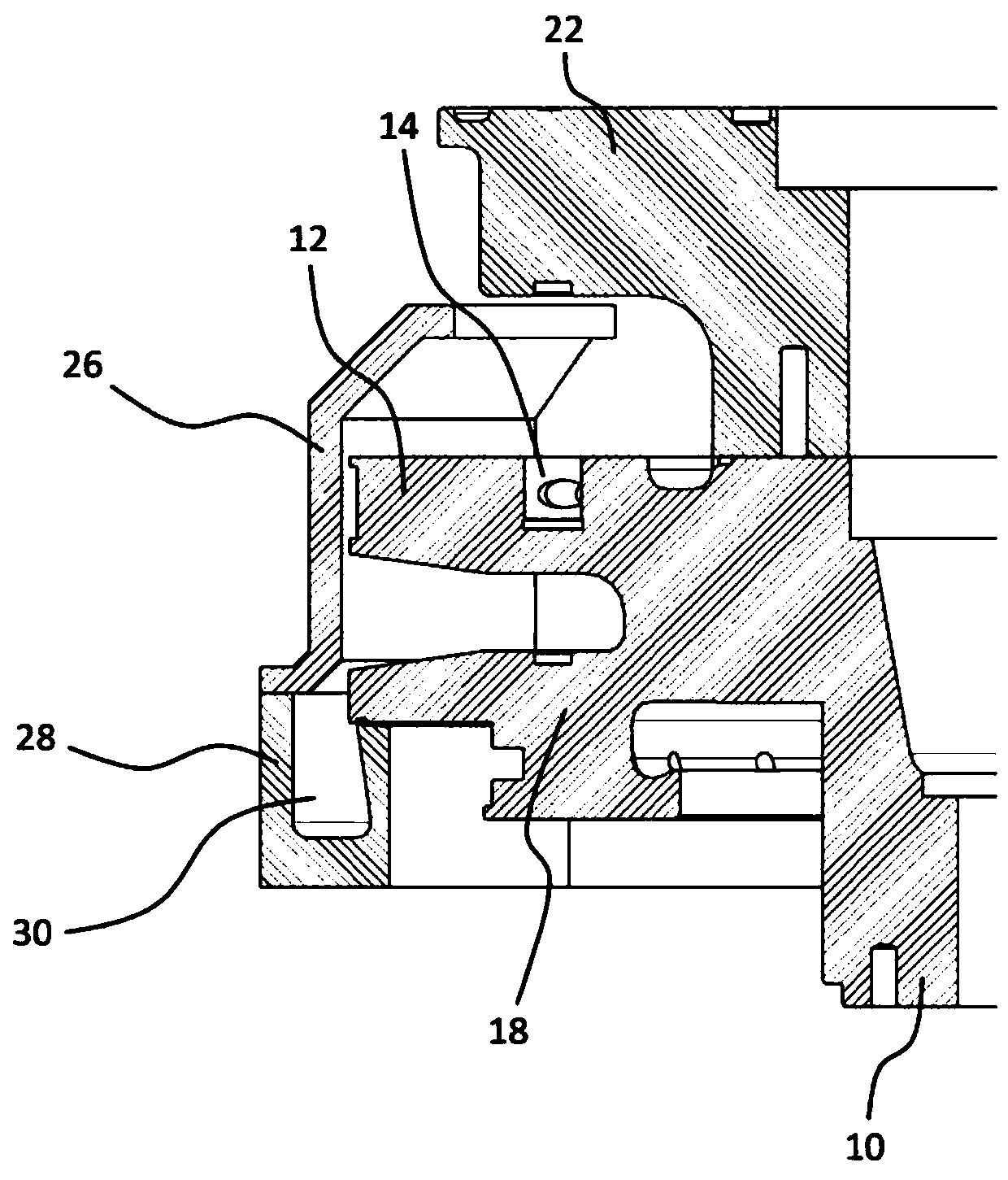
[0025]The rotor according to the invention shown in the figures is the rotor of a rotary press, in particular a rotary tablet press, for pressing eg powdery products into compacts, eg tablets. The rotor comprises a drive section 10 which is connected to a rotary drive for turning the rotor which is not shown in detail for reasons of simplicity. Die plate 12 is connected to drive section 10 . The die plate 12 has a plurality of sleeve receptacles 14 , in which die sleeves are inserted in the example, so that the die sleeves form the die holes of the die plate 12 . Also for reasons of simplicity, the die sleeve is not shown in the figures. The die plate 12 has a plurality of radial holes 16 on the peripheral side, into which locking screws for locking the die sleeve in the sleeve receptacle 14 can be inserted. This is known. In the example shown, the die disk 12 is designed ...


PUM


Abstract

A rotor for a rotary press used for pressing a product into a compressed object comprises a die plate which is rotatably driven by a rotational driving apparatus and has a die hole, upper punch seatswhich is synchronously rotated with the die plate and axially guides upward-punching, and lower punch seats which is synchronously rotated with the die plate and axially guides downward-punching. An annular discharge channel is configured to be in a fixed position and further configured to collect product residue from at least one of the die plate and the lower punch seat. The discharge channel additionally comprises a removal region where the product residue is configured to be removed from the annular discharge channel. A catch element is configured to rotate in sync with the die plate and is guided within the annular discharge channel to convey the product residue collected in the annular discharge channel to the removal region.

Description

technical field [0001] The invention relates to a rotor for a rotary press for pressing products into compacts, said rotor comprising a die disc with die holes driven in rotation by means of a rotary drive, rotating synchronously with the die disc An upper punch receptacle for axially guiding the upper punch and a lower punch receptacle for axially guiding the lower punch which rotate synchronously with the die plate. Background technique [0002] Such a rotor is known, for example, from patent document DE 10 2015 105 936 B4. In rotary presses, mostly powdered products are compressed into compacts, eg tablets. During the course of the pressing process, product residues are produced which accumulate, in particular, on the upper side of the die plate and on the upper side of the lower punch receptacle. Suction lines of a suction device, which is intended to suck up product residues, are therefore positioned at various points of the rotor, in particular at various points of t...

Claims


Application Information

Patent Timeline
Patent Type & Authority Applications(China)
IPC IPC(8): B30B11/16B30B15/02B30B15/00
CPCB30B11/165B30B15/022B30B15/0082B30B11/08B30B11/085B30B11/10
Inventor S·科尔贝J·纳韦F·沙德
Owner FETTE COMPACTING GMBH
Why Eureka
Try Eureka