Eureka AIR delivers breakthrough ideas for toughest innovation challenges, trusted by R&D personnel around the world.

Solid-liquid separation equipment for chemical production

A technology for solid-liquid separation and chemical production, which is applied in solid separation, chemical instruments and methods, and filtration and screening, etc. It can solve the problems of reduced separation efficiency, cumbersome operation, time-consuming and labor-intensive, etc., so as to reduce labor intensity, improve separation efficiency, and improve The effect of stability

Inactive Publication Date: 2020-03-17
陈超
View PDF8 Cites 1 Cited by
  • Summary
  • Abstract
  • Description
  • Claims
  • Application Information

AI Technical Summary

Problems solved by technology

The solid-liquid separation device for pharmaceutical and chemical equipment, through the movable plate installed in the inner cavity of the box and the round hole opened, the device can separate solid and liquid, very convenient to use, and the installed stretch cloth and sealing collar , so that the sealing of the device is very good, and the installed vibration motor, moving plate and spring make the connecting rod drive the movable plate to vibrate, so that the solid-liquid separation of the device is more convenient, but during use, the solid particles are separated by the filter If left in the chemical equipment, it is generally necessary to manually remove the solid particles. This treatment method is cumbersome, time-consuming and labor-intensive, increases the labor intensity of the staff, reduces the separation efficiency, and brings great inconvenience to the separation work. Therefore, , we propose a solid-liquid separation equipment for chemical production

Method used


Image

  • Solid-liquid separation equipment for chemical production
  • Solid-liquid separation equipment for chemical production
  • Solid-liquid separation equipment for chemical production

Examples


Embodiment Construction

[0020] The following will clearly and completely describe the technical solutions in the embodiments of the present invention with reference to the accompanying drawings in the embodiments of the present invention. Obviously, the described embodiments are only some, not all, embodiments of the present invention. Based on the embodiments of the present invention, all other embodiments obtained by persons of ordinary skill in the art without making creative efforts belong to the protection scope of the present invention.

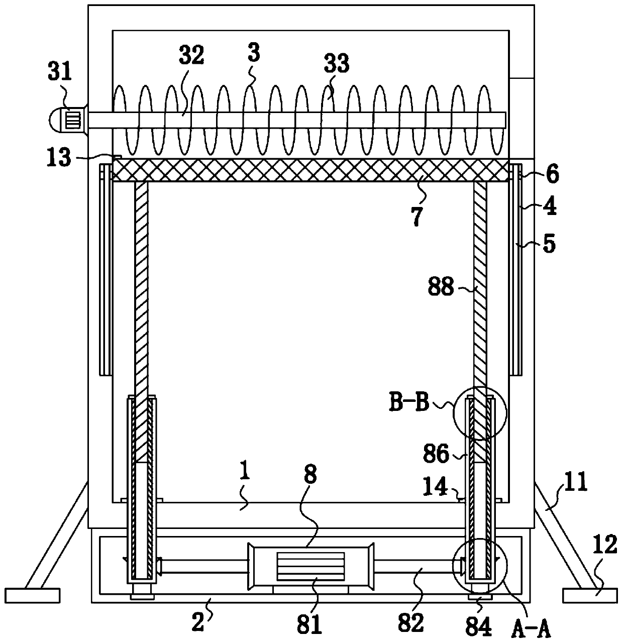
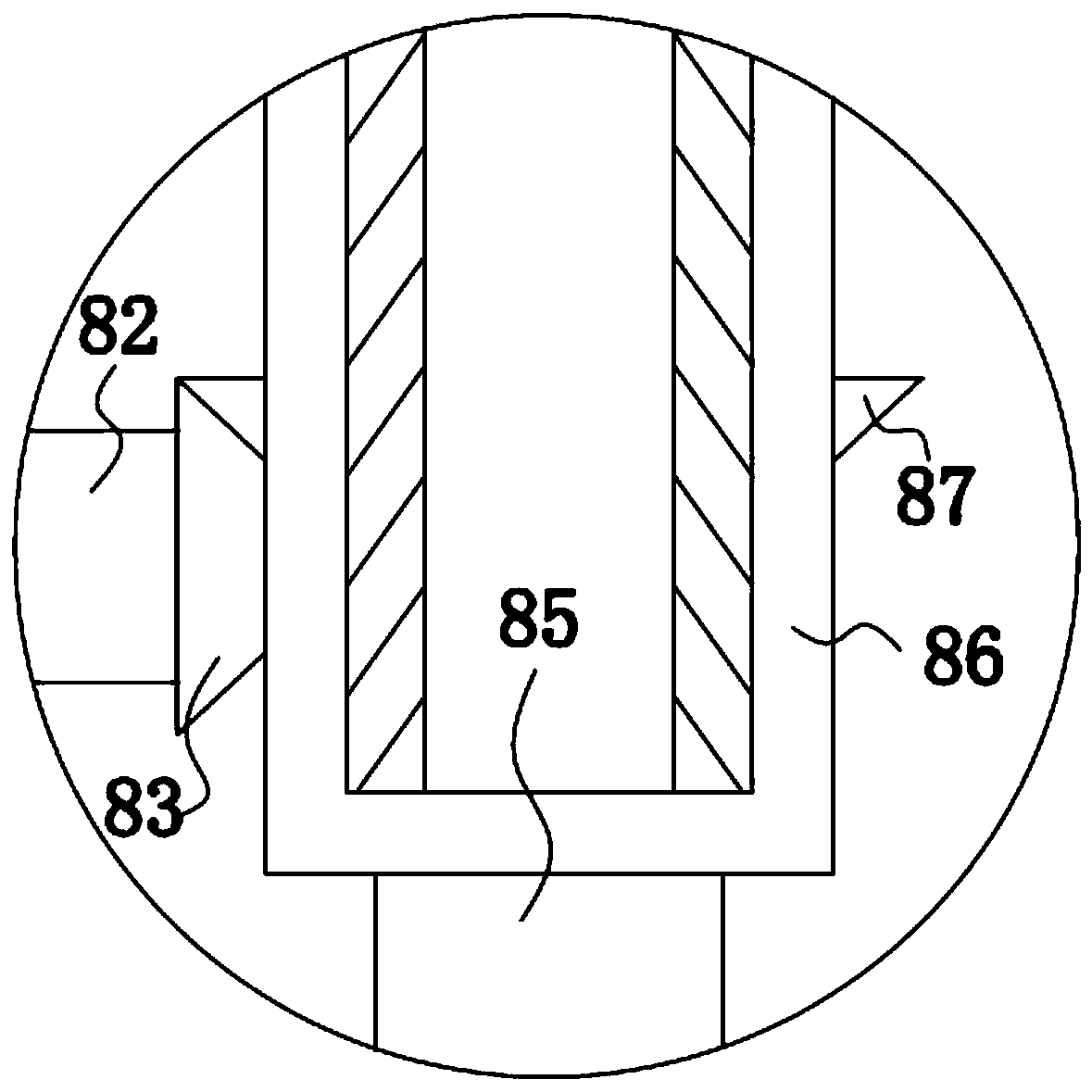
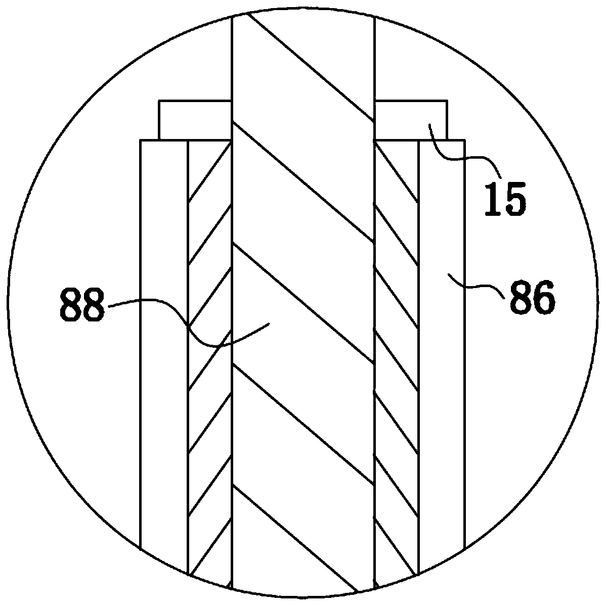
[0021] see Figure 1-4 , a solid-liquid separation device for chemical production, comprising a box 1 and a casing 2, the casing 2 is installed at the bottom of the box 1, the left and right sides of the inner wall of the box 1 are fixedly connected with support rods 11, the support rods 11 The bottom of the box is fixedly connected with a support block 12, and through the mutual cooperation of the support rod 11 and the support block 12, it plays a role in st...


PUM


Abstract

The invention discloses solid-liquid separation equipment for chemical production. The equipment comprises a box body and a shell, the shell is installed at the bottom of the box body, and a conveyingassembly is installed in the box body. A lifting mechanism is arranged; a double-shaft motor drives a first gear to rotate through a rotating shaft; the first gear drives a threaded sleeve to rotatethrough a second gear; the threaded sleeve is in threaded connection with a threaded rotating shaft; according to the lead screw principle, the threaded rotating shaft moves upwards in the threaded sleeve; a sieve plate moves upwards on the surface of a fixed rod through asliding block; solid particles generated in the box body are screened; and the limiting block limits the sieve plate; meanwhile, a driving motor drives the rotating shaft to drive spiral conveying blades to rotate, solid particles on the sieve plate are discharged out of the box body through a discharging opening, operation is easy, time and labor are saved, the labor intensity of workers is relieved, the separation efficiency is improved, and great convenience is brought to separation work.

Description

technical field [0001] The invention relates to the technical field of chemical equipment, in particular to a solid-liquid separation equipment for chemical production. Background technique [0002] At present, in the production of chemical industry, it is necessary to use separation equipment to separate solid particles from liquid, such as the application number: 201820335519.9, a solid-liquid separation device for pharmaceutical and chemical equipment, including a box, the box body The left end of the top is plugged with a feed pipe, and the middle section of the inner cavity of the box body is movably installed with a movable plate. And extend to the protruding rod outside the box body, the outer surface of the protruding rod is sleeved with a sealing collar connected with the box body, and the bottom of the left and right ends of the outer surface of the box body are fixedly installed with bottom plates. The solid-liquid separation device for pharmaceutical and chemica...

Claims


Application Information

Patent Timeline
Patent Type & Authority Applications(China)
IPC IPC(8): B07B1/28B07B1/46
CPCB07B1/28B07B1/46
Inventor 陈超
Owner 陈超
Why Eureka
Eureka Blog
Learn More