
A disc centrifuge drum

A disc centrifuge and drum technology, applied in the field of centrifuges, can solve the problems of single function, insufficient, poor separation effect, etc., and achieve the effect of improving the separation effect

Active Publication Date: 2021-12-10
黄春美
View PDF6 Cites 0 Cited by
  • Summary
  • Abstract
  • Description
  • Claims
  • Application Information

AI Technical Summary

Problems solved by technology

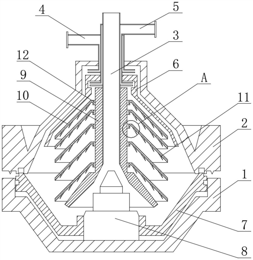
[0003] 1. In the existing centrifuge, the material rotates at a high speed through the rotor to make the material do centrifugal motion to separate different substances, and the different substances separated from the material are separated on the path at the disc, but because the traditional discs are in the The distribution is equidistant in the vertical direction, and the mixed content of the material separated near the bottom is higher, and the mixed content becomes smaller as the material goes up. On the one hand, the equidistant distribution will make there is not enough space between the bottom discs to separate Mix materials with high content, so that the unseparated materials will be forced to be squeezed to the outlets on both sides of the upper part due to the continuous addition of subsequent materials, and the materials that come out will often have a high solid residue content, resulting in separation The effect is poor, and when the solid residue moves to the upper discharge port, it will easily block the path of the upper bend, which will seriously lead to failure to discharge
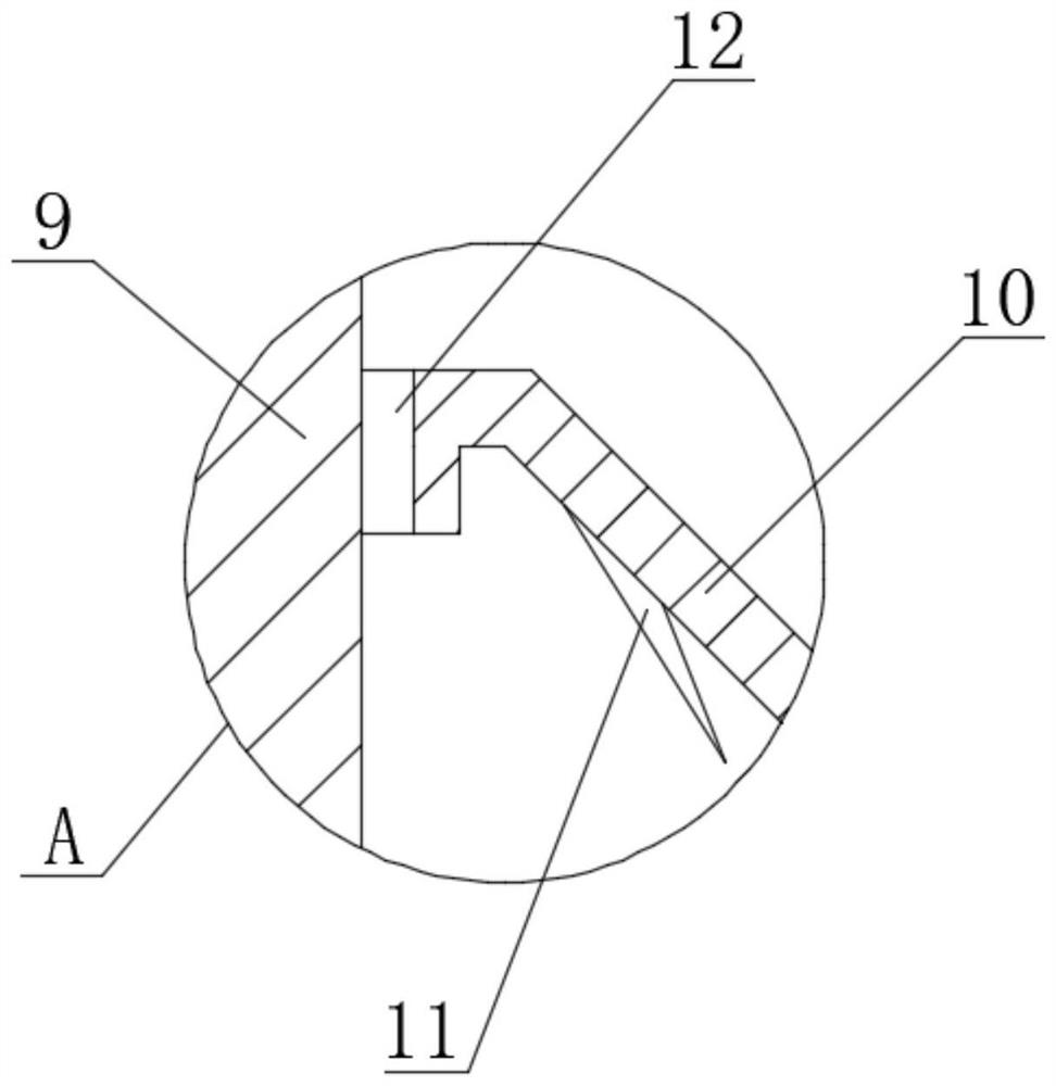
[0004] 2. In the disc separator, the material passes through the high-speed rotating rotor to separate the different phases of the material after centrifugal movement, and the different phases of the material are restricted and guided by the disc to the discharge path, but the existing disc The structure and function are single. Because the material at the feed port is continuously fed in, the traditional disc will not be able to completely slide down the solid phase material along the inclined wall of the disc to the drum due to the driving force of the material at the feed port. On both sides of the interior, part of the solid phase material is brought to the discharge port of the liquid phase with the material flow of the liquid phase, resulting in a high content of solid phase material in the liquid phase, thus affecting the separation effect

Method used


Image

  • A disc centrifuge drum
  • A disc centrifuge drum

Examples


Embodiment Construction

[0016] Next, the technical solutions in the embodiments of the present invention will be described in connection with the drawings of the embodiments of the present invention, and it is understood that the described embodiments are merely the embodiments of the present invention, not all of the embodiments. Based on the embodiments of the present invention, all other embodiments obtained by those of ordinary skill in the art are in the range of the present invention without making creative labor premise.

[0017] See Figure 1-2 A disc centrifuge drum, including the bottom case 1, the upper portion of the bottom case 1 is fixedly mounted, and the upper casing 2 is fixedly mounted, and the feed tube 3 is fixedly mounted. The first liquid phase, the other side of the feed tube 3 is fixedly mounted, and the outer side of the feed tube 3 is fixedly mounted, and the bottom fixing of the inner wall of the bottom shell 1 is fixed. The switching valve 7 is attached, the middle activity of ...


PUM


Abstract

The invention relates to the technical field of centrifuges, and discloses a disc centrifuge drum, which includes a bottom shell, and an upper shell is fixedly installed on the upper part of the bottom shell. The disc centrifuge drum, by changing the traditional equidistant Disc distribution, the discs are set to non-equal spacing, and the distance between the discs gradually increases from top to bottom. Since the material at the bottom of the drum has just been separated by centrifugal motion, the mixed content of different phases is high. , the larger distance between the discs near the bottom can make the flow velocity of the material at the bottom when passing between the discs lower than that of the original equidistant flow rate, which can make the different phases of the separated material have enough The time for more sufficient separation in the lower part, so that the solid phase content of the liquid phase estimated material entering the upper disc is greatly reduced, and the smaller disc distance accelerates the separation of the solid phase material and the separated liquid The phase material flows out, improving the separation effect of the separator.

Description

Technical field [0001] The present invention relates to the field of centrifuge, and is specifically a disc centrifuge drum. Background technique [0002] The disc centrifuge is a very common purification of dispersion substances in the industry. Its main role is to purify, hierarchically, and classification of materials, etc., the working principle is the material from the top of the drum from the top of the drum In the transfer drum, the material is rotated through the high speed of the centrifugal rotor of the bottom, so that the material is moved in which the material is centrifuged, and the different substances are separated from each other according to their material, and the solid residue is discharged from both sides. Then, from the top of the discharge opening, the separation purification of the material is realized, but there is always some problems in the existing disc centrifuge drum: [0003] 1. The material in the conventional centrifuge rotates high-speed rotation ...

Claims


Application Information

Patent Timeline
Patent Type & Authority Patents(China)
IPC IPC(8): B04B7/08B04B1/00
CPCB04B7/08B04B1/00
Inventor 张谷应
Owner 黄春美
Learn More