Vehicle-mounted multi-system combined antenna and positioning antenna

A technology for combining antennas and positioning antennas, which is applied in the direction of antennas, antennas suitable for movable objects, and antenna components.

Inactive Publication Date: 2020-03-13
SHENZHEN DINGYAO SCI & TECH
View PDF5 Cites 2 Cited by
  • Summary
  • Abstract
  • Description
  • Claims
  • Application Information

AI Technical Summary

Problems solved by technology

In addition, considering the mutual influence of integrated antennas, the performance of the antennas cannot be deteriorated to affect the use of the system, and reliability and cost must also be considered, which brings great challenges to the design of multi-system combined antennas. There is no such product before. Appear

Method used


Image

  • Vehicle-mounted multi-system combined antenna and positioning antenna
  • Vehicle-mounted multi-system combined antenna and positioning antenna
  • Vehicle-mounted multi-system combined antenna and positioning antenna

Examples


Embodiment 1

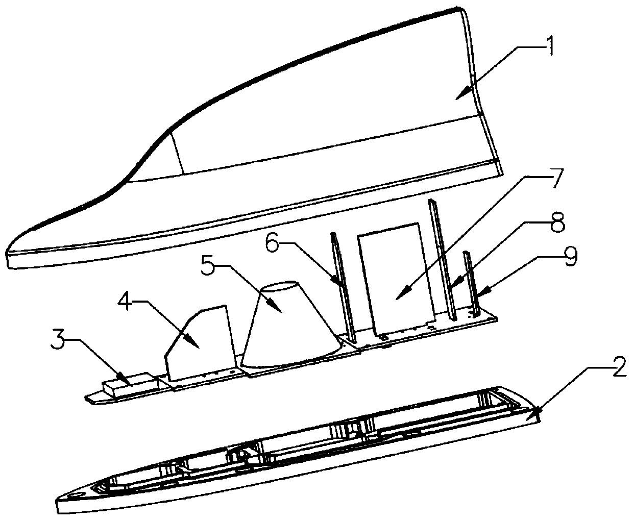
[0039] Please refer to figure 1 ,

[0040] This embodiment provides a vehicle-mounted multi-system combined antenna, such as figure 1 , the combined antenna includes a shark-fin-shaped radome 1 and an antenna base 2, and an accommodating cavity is formed between the radome 1 and the antenna base 2. The combined antenna also includes a first positioning antenna 3, a first communication antenna 4, a second positioning antenna 5, a first V2X antenna 6, a second communication antenna 7 and a second V2X antenna 8 arranged on the antenna base 2, the first The positioning antenna 3, the first communication antenna 4, the second positioning antenna 5, the first V2X antenna 6, the second communication antenna 7 and the second V2X antenna 8 are sequentially arranged on the radome 1 and the antenna along the front to the rear of the radome. In the accommodation cavity formed by the base 2, the front of the radome 1 is in the direction of the fish head of the fin-shaped radome, and the ...

Embodiment 2

[0054] Please refer to Figure 4 , the present embodiment provides a positioning antenna for a shark fin vehicle antenna, the positioning antenna (i.e. the second positioning antenna 5 in Embodiment 1) is a GNSS antenna, which includes a radiation base and a third feeder circuit board 52 , the third feeding circuit board 52 is arranged on the antenna base 2 , and the radiation base is vertically arranged on the third feeding circuit board 52 . In particular, in this embodiment, in order to save space and adapt to the shape of the shark-fin-shaped radome, and at the same time ensure the length of the antenna, the radiation base is designed as a hollow cone with a large bottom and a small top. In other embodiments It can also be conical. The outer surface of the radiation base is etched with four metal radiation arms 51 at equal intervals. The four metal radiation arms 51 are wound on the outer surface of the radiation base and rise in a spiral shape. Each metal radiation arm 51...


PUM


Abstract

The invention relates to the technical field of radio frequency antennas., in particular to a vehicle-mounted multi-system combined antenna and a positioning antenna. The combined antenna comprises ashark fin-shaped antenna cover and an antenna base, and further comprises a first positioning antenna, a first communication antenna, a second positioning antenna, a first V2X antenna, a second communication antenna and a second V2X antenna which are sequentially arranged in the containing cavity from front to back of the antenna cover. According to the invention, the working frequency and transceiving characteristics of each antenna are comprehensively considered; the appearance shape of the shark fin antenna is not changed; the arrangement mode of the combined antenna is provided; a main antenna required by an Internet of Things automobile is integrated in an accommodating cavity of a shark fin antenna; according to the invention, stable communication and accurate positioning of the Internet of Things automobile are ensured, and the mutual coupling influence among the antennas is minimized through the arrangement mode, so that the directional diagram of the antennas is optimal, a plurality of antennas are ensured to work normally at the same time, and the requirements of stable communication and accurate positioning are met.

Description

technical field [0001] The invention relates to the technical field of radio frequency antennas, in particular to a vehicle-mounted multi-system combined antenna and a positioning antenna. Background technique [0002] With the advent of the era of automotive intelligent networking and autonomous driving, the addition and integration of various communication and navigation systems has led to a rapid increase in the type and number of vehicle antennas compared to before. At present, the best place to place the body antenna is the roof position, which is shaped like a shark fin. Generally, it is integrated with a 4G main antenna, a 4G secondary antenna and a low-precision GPS antenna to meet basic communication and navigation requirements. From the perspective of manufacturing and use, the addition of new communication and navigation antennas still needs to meet the original antenna outline as much as possible and meet the aerodynamic drag reduction characteristics. In additi...

Claims


Application Information

Patent Timeline
Patent Type & Authority Applications(China)
IPC IPC(8): H01Q1/32H01Q1/12H01Q21/24
CPCH01Q1/1207H01Q1/125H01Q1/32H01Q21/24
Inventor 俞江李鹏图杨伟城
Owner SHENZHEN DINGYAO SCI & TECH
Why Eureka
Try Eureka