Method for calculating apparent conductivity of electromagnetic field of frequency domain electrical source

A technology of apparent conductivity and calculation method, which is applied in electric/magnetic exploration, ground resistance measurement, radio wave measurement system, etc. It can solve inaccurate calculation of apparent resistivity, numerical error, and affect the efficiency and accuracy of data interpretation, etc. question

Pending Publication Date: 2020-03-13
EAST CHINA UNIV OF TECH
View PDF1 Cites 4 Cited by
  • Summary
  • Abstract
  • Description
  • Claims
  • Application Information

AI Technical Summary

Problems solved by technology

[0003] At present, studies on the calculation of the apparent resistivity of the whole region have been carried out at home and abroad. Most of the definition methods of the apparent resistivity of the whole region use the measurement of the electric field x component E in the Cartesian coordinate system. x To calculate, this method can solve most of the measurement area, but based on the tangential component of the observation point in the cylindrical coordinate system The observation area range is much larger than E x weight
In addition, by the electric field E x or To define the apparent resistivity of the whole area, it is usually necessary to select an appropriate initial value and use iterative solution formulas for iterative approximation to calculate the apparent resistivity parameters. The selection of initial values ​​and iterative formulas often result in apparent resistivity (apparent conductivity) Inaccurate calculations lead to numerical errors and affect the efficiency and accuracy of later data interpretation

Method used


Image

  • Method for calculating apparent conductivity of electromagnetic field of frequency domain electrical source
  • Method for calculating apparent conductivity of electromagnetic field of frequency domain electrical source
  • Method for calculating apparent conductivity of electromagnetic field of frequency domain electrical source

Examples


Embodiment Construction

[0060] Below in conjunction with accompanying drawing and specific embodiment the present invention is described further:

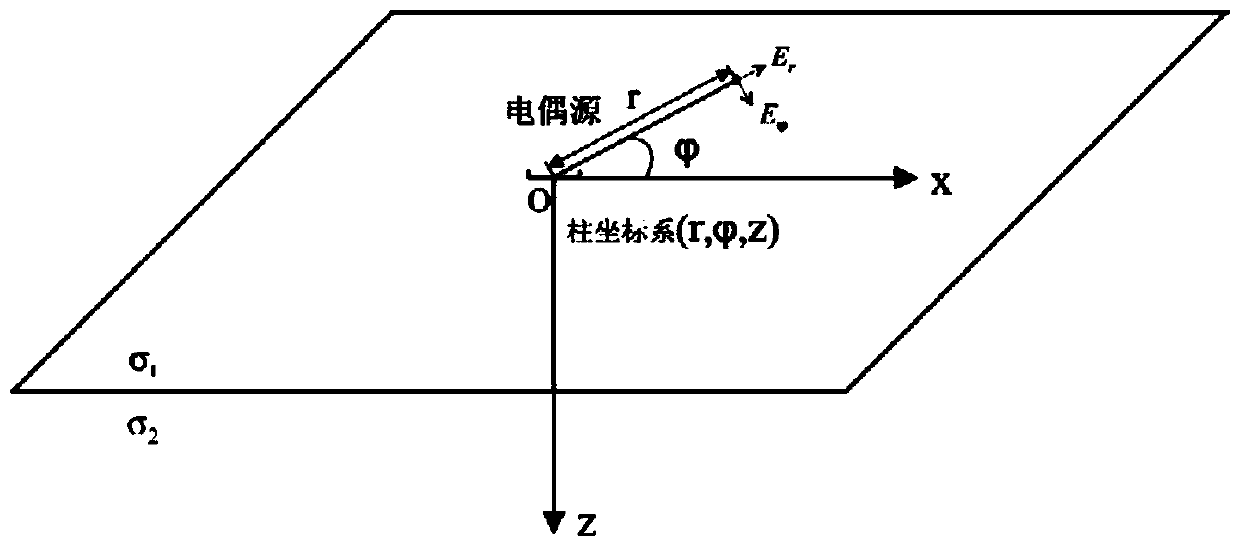
[0061] See figure 1 As shown, a new frequency-domain electric source electromagnetic field apparent conductivity calculation method provided by the present invention comprises the following steps:

[0062] (1) Arrange the horizontal galvanic source in the designated exploration area, connect the AC transmitting power supply and the transmitter, measure the length dl of the galvanic source, record the coordinates of power supply points A and B, and record the current I sent by the transmitter. In addition, calculate the angle between the observation point and the positive direction of the dipole moment

[0063] (2) According to the exploration requirements, arrange the observation network, select the frequency observation range and the observation fan-shaped area, record the coordinates of the observation points on each observation line in the observat...


PUM


Abstract

The invention discloses a method for calculating the apparent conductivity of an electromagnetic field of a frequency domain electrical source. The method comprises the following steps: (1) arranginga power supply electrode and a transmitting power supply in a specified exploration area; (2) arranging an observation network, and selecting a frequency range and an observation fan-shaped area; recording I of current information transmitted by a transmitter, and observing a tangential component E<phi> or a normal component E<r> of a multi-frequency-point electromagnetic field at one time at a receiver end; (3) calculating the derivatives round(E<phi>) / round(f) and round(E<r>) / round(f) of the electric field tangential component E<phi> or normal component E<r> of the corresponding frequency point combination to the frequency f by adopting a second-order difference technology, and storing the calculated partial derivative information; and (4) calculating the apparent conductivity of a frequency domain electric dipole source by using the derivatives round(E<phi>) / round(f) and round(E<r>) / round(f). The method is suitable for observing the electrical distribution of an underground structure in the whole domain. Only electric field data in one direction needs to be measured, the field acquisition cost is low, the observation efficiency is high, and the requirement for observation equipment is low.

Description

technical field [0001] The invention relates to the frequency domain electromagnetic method apparent conductivity measurement method applied in the field of geophysics, in particular to the normal component E of the measurement observation point r and the tangential component To calculate the conductivity method, this method can effectively improve the accuracy of apparent conductivity calculation. Background technique [0002] In the application of geophysical frequency domain electromagnetic prospecting, apparent resistivity (the reciprocal of apparent conductivity) is an important parameter to evaluate the conductivity of underground rocks (ores). Usually, the apparent resistivity is related to factors such as rock (ore) composition, structure and measuring devices of the underground medium, and it is a comprehensive effect of underground rock (ore). For example, Controlled Source Audio-frequency Magnetotellurics (CSAMT) is an active frequency-domain electromagnetic pr...

Claims


Application Information

Patent Timeline
IPC IPC(8): G01V3/08G01V3/38G01R27/20
CPCG01V3/08G01V3/38G01R27/20Y02A90/30
Inventor 周峰张志勇陈辉李勇李曼
Owner EAST CHINA UNIV OF TECH
Why Eureka
Try Eureka