Quick-disassembly winding device

A rewinding device and quick-release technology, which can be used in strip winding, transportation and packaging, thin material handling, etc., and can solve problems such as low blanking work efficiency.

Active Publication Date: 2020-03-10
GUANGZHOU ZHUOYUE POWER NEW ENERGY CO LTD
View PDF5 Cites 1 Cited by
  • Summary
  • Abstract
  • Description
  • Claims
  • Application Information

AI Technical Summary

Problems solved by technology

[0004] The present invention intends to provide a quick-detachable rewinding device to solve the problem that the existing grid rewinding device has low working efficiency of blanking

Method used


Image

  • Quick-disassembly winding device
  • Quick-disassembly winding device
  • Quick-disassembly winding device

Examples


Embodiment

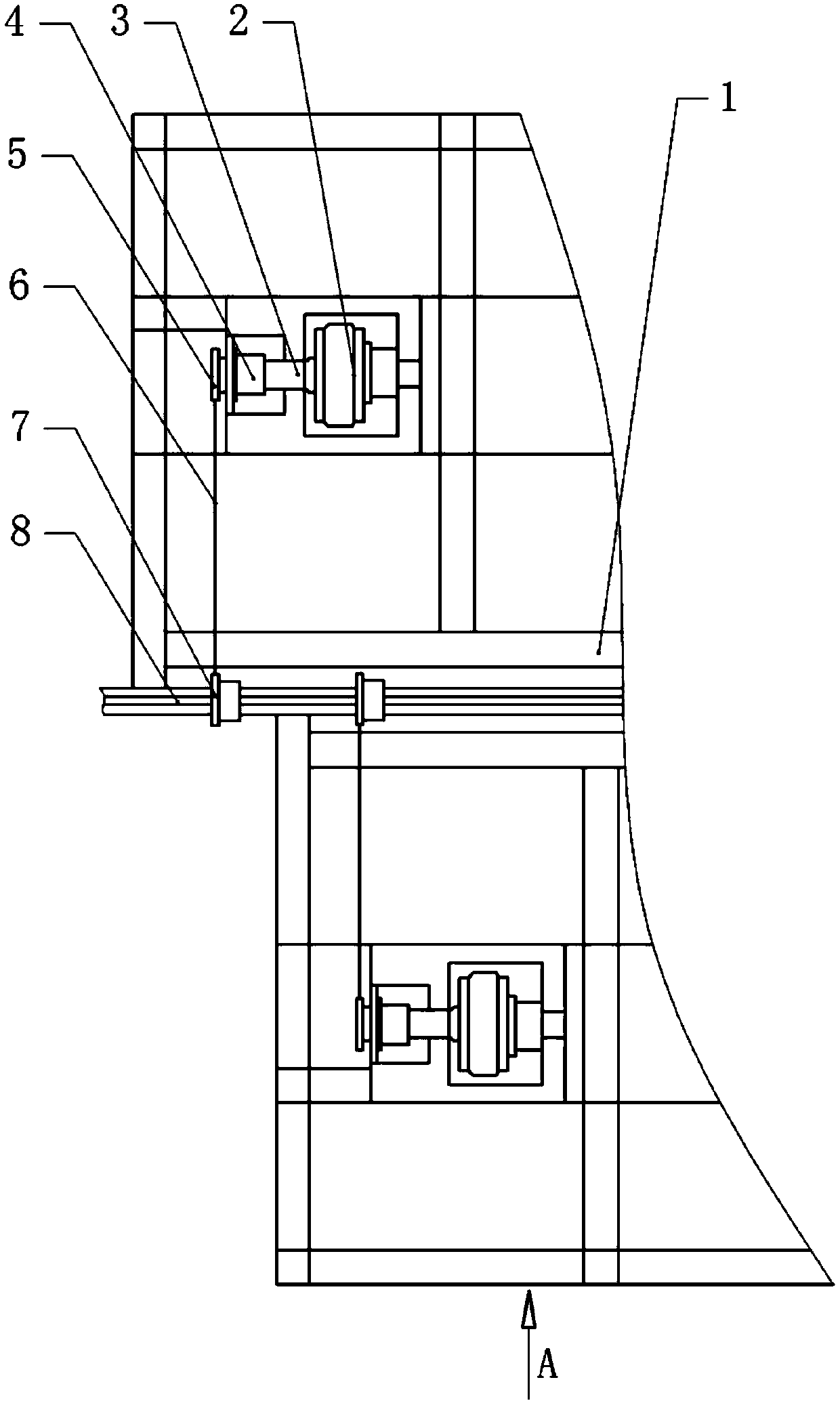
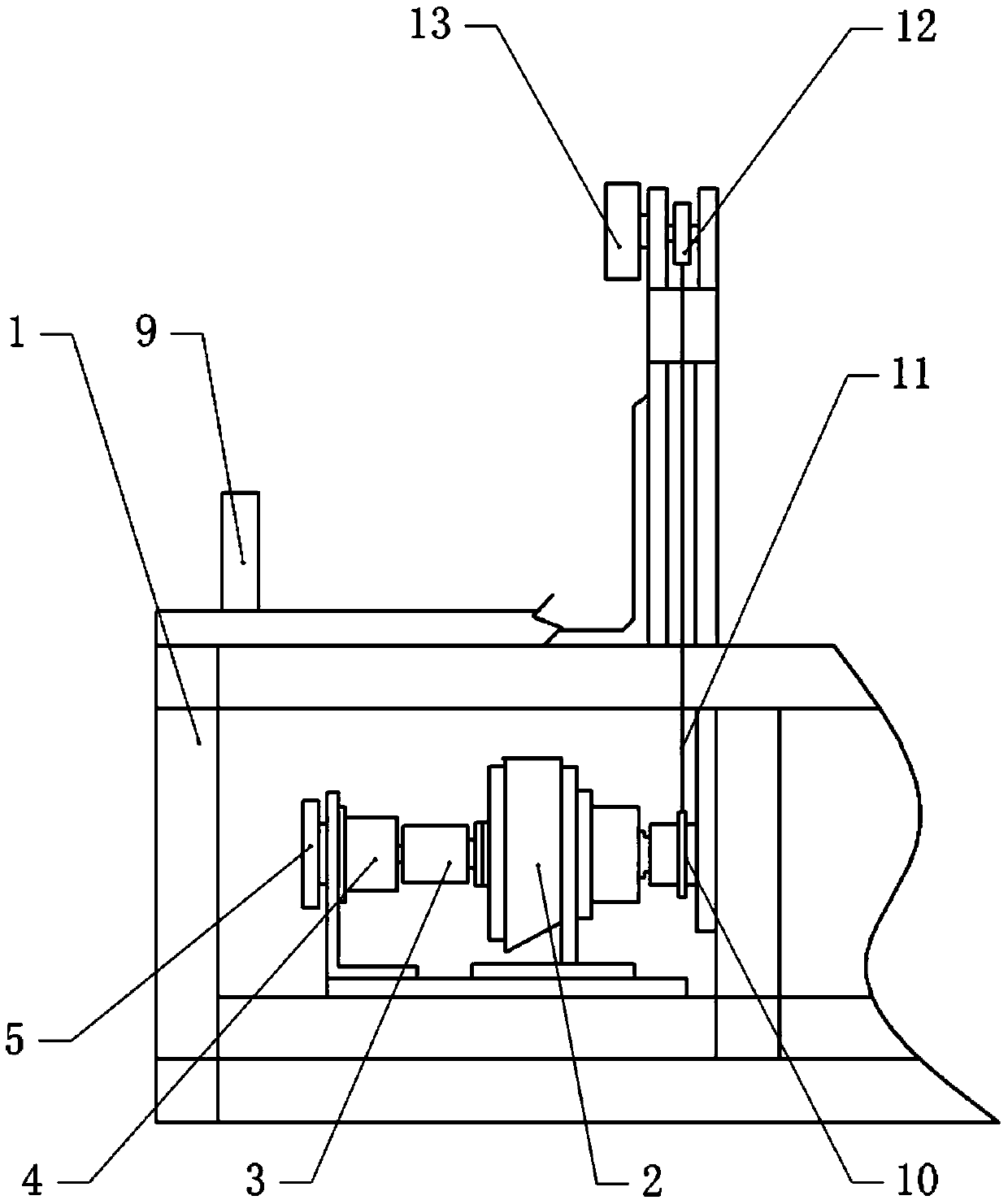
[0029] A quick-release winding device, basically as attached figure 1 And Figure 4 As shown, the frame 1 and the intermittent transmission mechanism installed on the frame 1 are included.

[0030] As attached figure 1 , 2 3, the frame 1 is provided with a drive shaft 8 along the transverse direction of the frame 1, and two bearings and a bearing seat for mounting the bearings are provided along the axial direction of the drive shaft 8. The bearing seat is fixed on the frame 1.

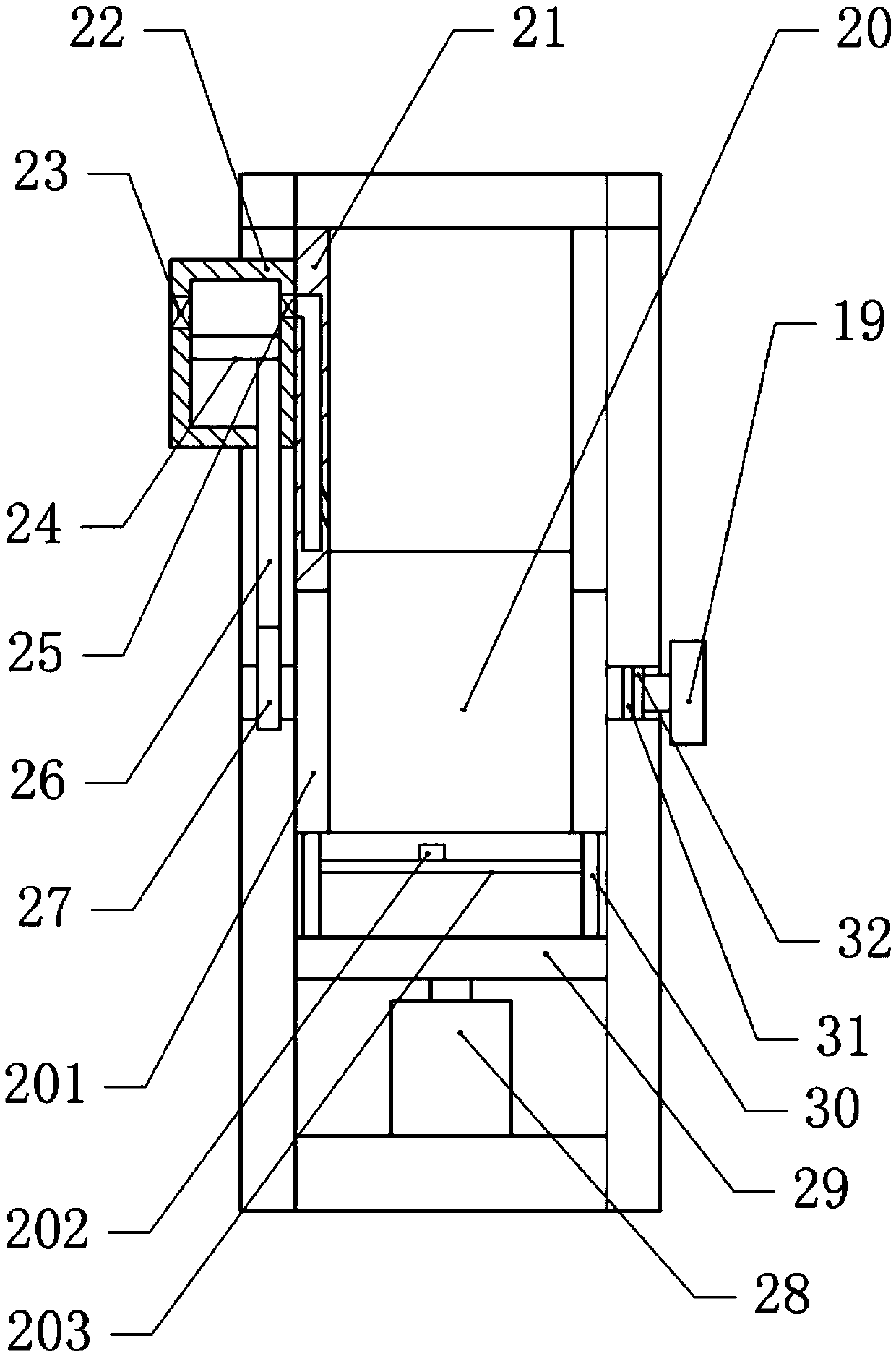
[0031] As attached figure 1 , The frame 1 on both sides of the driving shaft 8 is respectively provided with a winding mechanism, and the winding mechanisms on both sides are arranged back and forth along the axial direction of the driving shaft 8. Attached figure 2 And image 3 , The winding mechanism includes a winding roller 20 and a winding frame fixed on the frame 1. The winding roller 20 is arranged along the axial direction of the driving shaft 8, and both ends of the winding roller 20 are rotatably...


PUM


Abstract

The invention relates to the technical field of grid weaving manufacturing, and discloses a quick-disassembly winding device. The quick-disassembly winding device comprises a rack and an intermittenttransmission mechanism. A driving shaft is rotationally connected in the transverse direction of the rack, at least one winding mechanism is arranged on the rack on the two sides of the driving shaft,and the winding mechanisms on the two sides are arranged on the front and back in the axial direction of the driving shaft. The intermittent transmission mechanism is connected with the driving shaftand drives the driving shaft to intermittently rotate. The winding mechanism comprises a winding roller and a winding frame fixed on the rack, and the winding roller is arranged in the axial direction of the driving shaft. The two ends of the winding roller are rotationally connected on the winding frame, and the driving shaft can drive the winding roller to synchronously rotate. According to thescheme, the driving shaft is intermittently transmitted by an intermittent transmission mode, and therefore the winding roller intermittently rotates to wind a grid. When the intermittent mechanism stops, the winding roller can be replaced quickly.

Description

Technical field [0001] The invention relates to the technical field of grid weaving manufacturing, in particular to a quick-release winding device. Background technique [0002] The grid is an important component of the lead storage battery and is used to coat active materials to realize the charging and discharging functions of the storage battery. The current grids include drawing and casting. The mesh of the drawing is generally woven by a braiding machine. In the process of weaving the grid by the braiding machine, the formed grid needs to be continuously collected. The grid winding device is a kind of equipment specially used for winding the grid with the braiding machine. The grid woven by the braiding machine is rolled into a roll by the grid winding device. In order to improve the production efficiency of the braiding machine, the usual method is to increase the width of the braiding machine. However, if the width of the braiding machine is too large, the grid rolls woun...

Claims


Application Information

Patent Timeline
Patent Type & Authority Applications(China)
IPC IPC(8): B65H18/12B65H23/04B65H23/195B65H23/032B65H23/02B65H26/08B65H26/04
CPCB65H18/12B65H23/044B65H23/195B65H23/0328B65H23/0204B65H26/08B65H26/04B65H2515/31B65H2511/14B65H2220/01Y02E60/10
Inventor 何幸华黎少伟李政文何可立马俊
Owner GUANGZHOU ZHUOYUE POWER NEW ENERGY CO LTD
Why Eureka
Try Eureka