
A Dynamically Configurable High-Precision and High-Reliability Clock Network

A clock network, high-precision technology, used in signal generation/distribution, instruments, electrical digital data processing, etc., can solve the problems of poor clock synchronization accuracy, non-independent clock units, unstable circuit operation, etc. Evaluate and expand, realize the effect of synchronous reconstruction, and prolong the working life

Active Publication Date: 2020-11-20
BEIJING RES INST OF SPATIAL MECHANICAL & ELECTRICAL TECH
View PDF10 Cites 0 Cited by
  • Summary
  • Abstract
  • Description
  • Claims
  • Application Information

AI Technical Summary

Problems solved by technology

[0008] The problem solved by the technology of the present invention is: various clock synchronization deviations caused by device delay and system noise. Within the required range, solve the unstable operation of the circuit due to poor clock synchronization accuracy; the present invention can eliminate the problem of decreased synchronization accuracy due to aging of the clock device through remote configuration, and greatly extend the working time of the clock network; the solution of the present invention The clock unit is not independent, the clock network parameters cannot be configured, and the scalability and maintainability of the clock network are poor

Method used

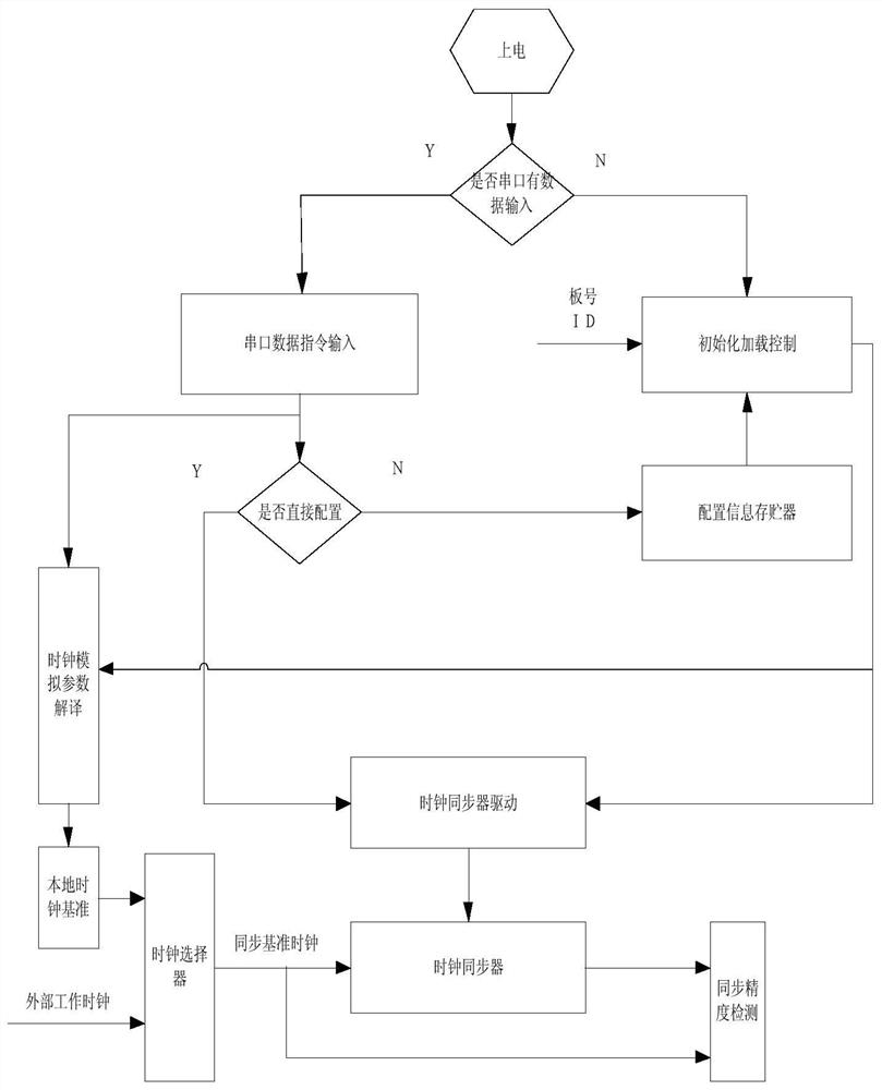

Image

  • A Dynamically Configurable High-Precision and High-Reliability Clock Network
  • A Dynamically Configurable High-Precision and High-Reliability Clock Network
  • A Dynamically Configurable High-Precision and High-Reliability Clock Network

Examples


Embodiment Construction

[0042] The present invention is further described in conjunction with accompanying drawings.

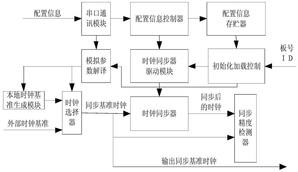
[0043] Each network unit follows the figure 1 The daisy-chain ring topology structure constitutes a clockwise end-to-end clock network, in which the clock reference flow is the clock reference of each clock unit, which can be selected from the local reference of the unit and the external input reference, and the upper-level network unit can output The clock reference is used as the clock reference of the external input of the next-level network unit of the clock network; the configuration information flow is the configuration information channel of each network unit, and it is also connected clockwise according to the daisy chain to form a ring topology, so that the configuration information flow can be Traverse the entire network in circular order.

[0044] network unit ( figure 2 ) includes a serial port communication module, a configuration information controller, a configuration...


PUM


Abstract

The invention discloses a dynamically configurable high-precision and high-reliability clock network. The network comprises multiple several network units. All the network units form a clock network with clockwise end-to-end links according to a daisy chain annular topological structure. Wherein the clock reference flow is the clock reference of each clock unit and is selected from the local reference and the external input reference of the network unit, and the clock reference output by the previous-stage network unit is used as the external input clock reference of the next-stage network unit; wherein the configuration information flow is a configuration information channel of each network unit, and the configuration information flow is clockwise and sequentially connected in series to form a ring topology structure according to the daisy chain, so that the configuration information flow traverses the whole clock network according to a ring sequence. According to the invention, the problem that the synchronization precision is reduced due to aging of the clock device can be eliminated through remote configuration, and the working time of the clock network is greatly prolonged.

Description

technical field [0001] The invention relates to a dynamically configurable clock network, which is used for building a clock system of a digital circuit with high reliability, long life and high stability. [0002] technical background [0003] At present, the fully synchronous clock network of general digital circuits is constructed by isolated clock units, and the clock network is designed as a dedicated clock network according to specific requirements. The disadvantage is that the clock network itself is fixed and cannot be expanded, and its fault tolerance is poor. The more complex the synchronization system, the more corresponding synchronization units, the greater the development cost to eliminate the synchronization deviation of the entire network, and it is difficult to standardize. [0004] In the use of the clock network, with the passage of time, the aging of the clock components, the performance degradation, the synchronization accuracy will continue to decline, ...

Claims


Application Information

Patent Timeline
Patent Type & Authority Patents(China)
IPC IPC(8): G06F13/42G06F1/12
CPCG06F1/12G06F13/4282G06F2213/0002
Inventor 万旻李硕李恺黄义成桂梅刘涛王蕴龙崔雪楠柴凤萍王磊耿树芳张峰瑞
Owner BEIJING RES INST OF SPATIAL MECHANICAL & ELECTRICAL TECH
Learn More