Pile foundation digging machine for building foundation engineering

A basic engineering and hole-digging machine technology, which is applied in construction, rotary drilling rigs, drilling equipment and methods, etc., can solve the problems of life-threatening construction personnel, harsh working environment, and many safety hazards, so as to avoid the vibration of the drill bit and drill The effect of high hole stability and low production cost

Pending Publication Date: 2020-03-06
湖南鼎功岩土特种设备有限公司
View PDF0 Cites 4 Cited by
  • Summary
  • Abstract
  • Description
  • Claims
  • Application Information

AI Technical Summary

Problems solved by technology

[0003] The construction of cast-in-situ piles is divided into two parts: hole-forming and pile-forming. Hole-forming is the first link in the construction of cast-in-place piles. The rotary excavators in conventional bored piles use mud wall protection, and the diameter is 0.8m-1.5m. The pile foundation construction is more effective, but for the large-aperture construction of 1.5m or even more than 2.5m, the existing large-aperture rotary excavator is expensive, and most of them are foreign equipment. On the one hand, the whole machine is heavy and the cost of digging is high. At the same time, a special crane is required to be used together, which increases the cost and difficulty of operation, and it is not suitable for construction in places with many urban buildings; Swinging and big vibration of the drill bit can easily cause deflection of the pile hole and damage to the drill bit system, resulting in failure of construction; manual digging is often used for large-aperture construction, and the construction progress of manual digging piles is slow. The working environment is harsh, the labor intensity is high, the efficiency of digging holes is low, and there are many safety hazards, such as water seepage at the bottom of the hole, methane, landslides, etc., will cause life danger to the construction workers

Method used


Image

  • Pile foundation digging machine for building foundation engineering
  • Pile foundation digging machine for building foundation engineering
  • Pile foundation digging machine for building foundation engineering

Examples


Embodiment Construction

[0028] The technical solutions provided by the present invention will be further described below in conjunction with the accompanying drawings and embodiments.

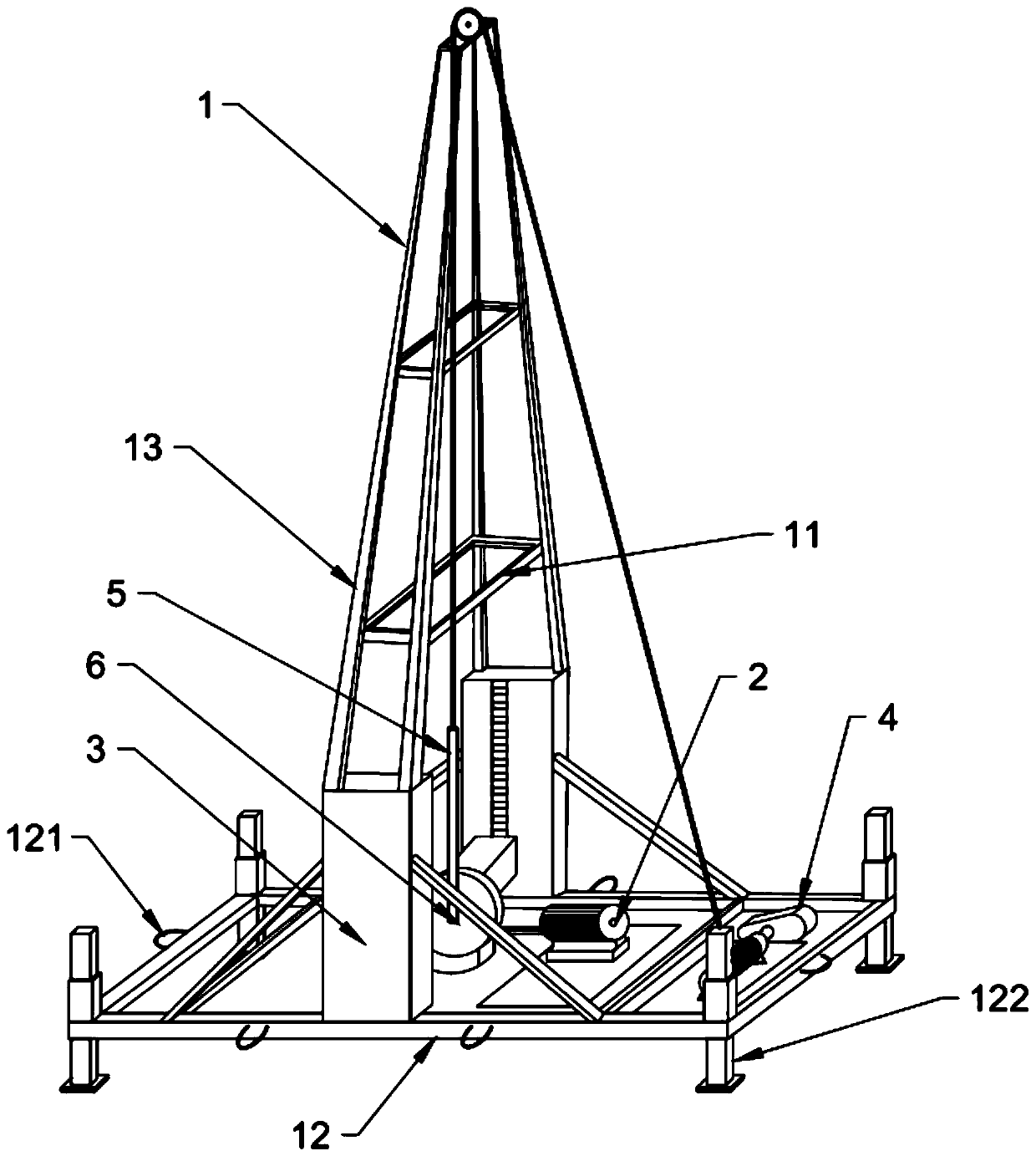
[0029] Please also refer to Figure 1-Figure 9, a pile foundation hole digging machine for building foundation engineering, including a drill frame 1, a power head 2, a hydraulic vertical lift frame 3, a winch 4, a telescopic pull rod 5 and a drill mechanism 6, and the drill frame 1 includes an upper support ring 11. The lower support circle 12 and the inclined strut 13, the power head 2, the hydraulic vertical lifting frame 3 and the winch 4 are all arranged on the lower support ring 12, and the two hydraulic vertical lifting frames 3 are used to support and raise the drill bit Mechanism 6, in order to replace the drill bit mechanism 6, the power head 2 is arranged between two hydraulic vertical lifting frames 3, and is used to drive the telescopic pull rod 5 to rotate, and the upper bracket circle 11 is connected wi...


PUM


Abstract

The invention relates to a pile foundation digging machine for building foundation engineering. The pile foundation digging machine for building foundation engineering comprises a drill stand, a powerhead, two hydraulic vertical lifting frames, a winch, a telescopic drill pipe and a drill bit mechanism. The drill stand comprises an upper bracket ring, a lower bracket ring and diagonal struts. Thepower head, the hydraulic vertical lifting frames and the winch are arranged on the lower bracket ring, the two hydraulic vertical lifting frames are used for supporting and lifting the drill bit mechanism for the convenience of replacing the drill bit mechanism, the power head is arranged between the two hydraulic vertical lifting frames for driving a telescopic pull rod to rotate, the upper bracket ring is connected to the top ends of the hydraulic vertical lifting frames through the diagonal struts, the winch is arranged at one end of the lower bracket ring, the upper bracket ring is connected to the telescopic pull rod through a steel wire rope, and the telescopic pull rod is connected to the drill bit mechanism. The pile foundation digging machine is simple and light and convenient,low in manufacturing cost, suitable for various different pile driving environments and bore diameters, strong in chambering ability and high in drilling stability, and can lower the labor cost, avoidpotential safety hazards of a manual hole digging pile and improve the construction efficiency and the chambering efficiency greatly.

Description

technical field [0001] The invention relates to the field of building pile foundation engineering, in particular to a pile foundation hole digging machine used for building foundation engineering. Background technique [0002] With the development of my country's modernization construction, there are more and more high-rise and super high-rise buildings in engineering construction. Due to the huge load from the upper part of the foundation construction of high-rise buildings, the general foundation is difficult to bear and special treatment must be carried out to achieve the design. To meet the requirements of foundation bearing capacity and settlement, the implementation of reaming construction on pile foundation can greatly improve the bearing capacity of single pile and save engineering cost. [0003] The construction of cast-in-situ piles is divided into two parts: hole-forming and pile-forming. Hole-forming is the first link in the construction of cast-in-place piles. Th...

Claims


Application Information

Patent Timeline
Patent Type & Authority Applications(China)
IPC IPC(8): E21B3/02E21B15/00E21B21/00E21B10/43E21B10/32E21B12/04
CPCE21B3/02E21B10/32E21B10/43E21B12/04E21B15/003E21B21/00
Inventor 唐勋刘华夏刘晓明龚石神吴琼熊象
Owner 湖南鼎功岩土特种设备有限公司
Why Eureka
Try Eureka