Door sliding block and door sliding block self-checking system

A technology of self-checking system, slide block, applied in the direction of lifts, elevators in buildings, transportation and packaging

Active Publication Date: 2020-03-03
SHANGHAI MITSUBISHI ELEVATOR CO LTD
View PDF13 Cites 0 Cited by
  • Summary
  • Abstract
  • Description
  • Claims
  • Application Information

AI Technical Summary

Problems solved by technology

[0006] The technical problem to be solved by the present invention is that it can automatically monitor the wear condition of the elevator door slider, and has a simple structure without disturbing noise.

Method used


Image

  • Door sliding block and door sliding block self-checking system
  • Door sliding block and door sliding block self-checking system
  • Door sliding block and door sliding block self-checking system

Examples


Embodiment 1

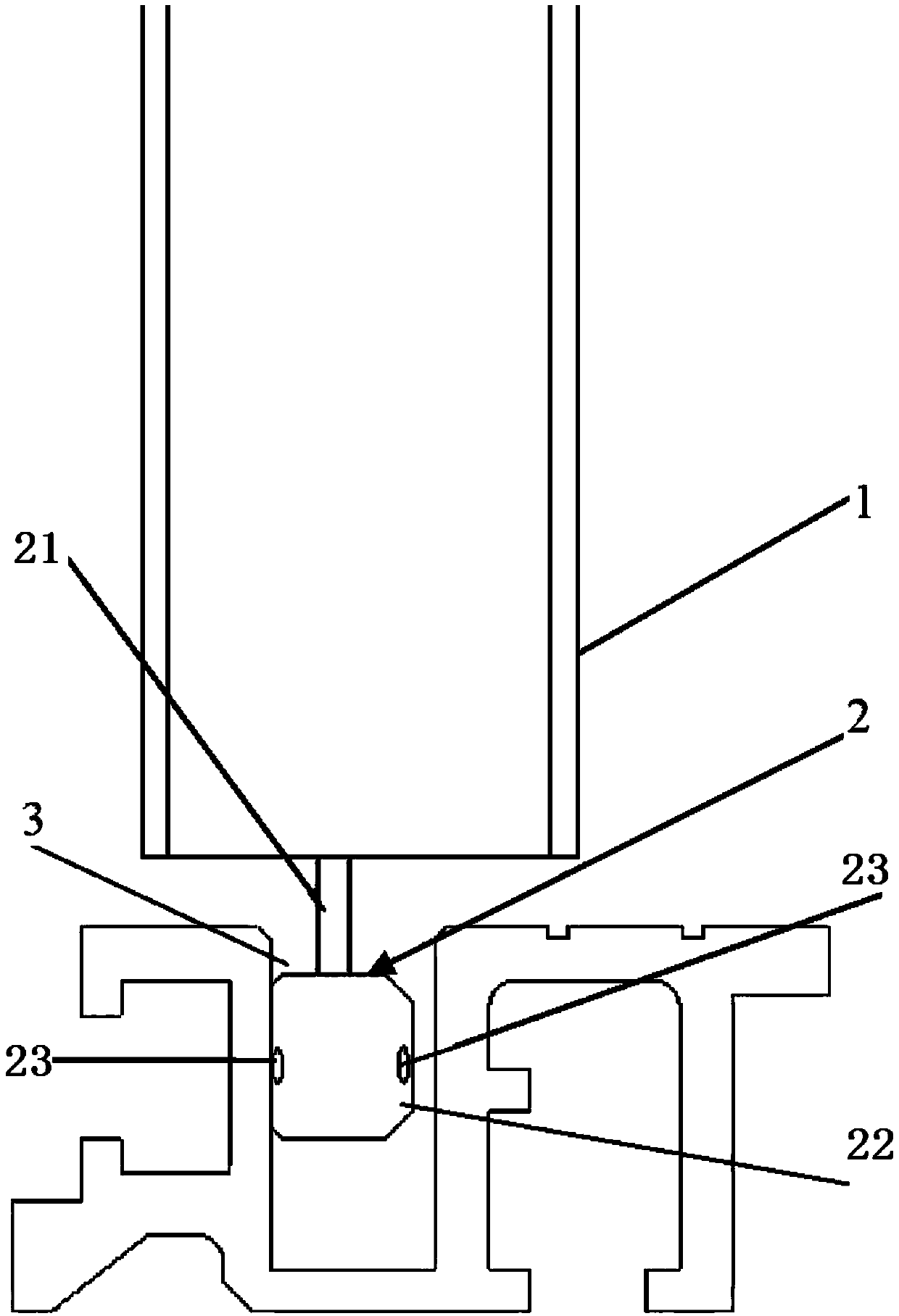
[0057] Such as figure 1 As shown, the door slider self-inspection system includes elevator door 1, door slider 2, sill groove 3, and sonar receiver;

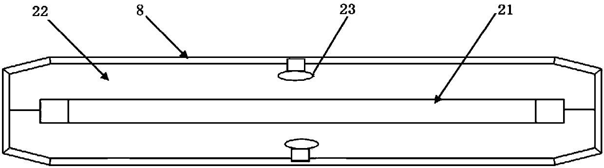
[0058] Such as figure 2 As shown, the door slider 2 includes a steel plate 21 and an air cushion 22;

[0059] The air cushion 22 is formed with a cavity;

[0060] The front and back sides of the steel plate 21 are respectively fixed with air cushions 22;

[0061] The upper end of the steel plate 21 of the door slider 2 is fixedly connected to the bottom of the elevator door 1;

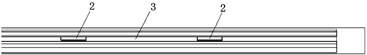
[0062] The door slider 2 is placed in the sill groove 3, and slides in the sill groove 3 with the opening and closing of the elevator door 1;

[0063] The front and back of the steel plate 21 are parallel to the friction surface of the sill groove 3;

[0064] The surface of the air cushion 22 away from the steel plate is parallel to the friction surface of the sill groove 3;

[0065]The outer surface of the air cushion 22 away from the steel plate...

Embodiment 2

[0079] Based on the door slider self-inspection system of Embodiment 1, the upper part of the steel plate 21 of the door slider 2 is processed with pin holes, and the bottom of the elevator door is provided with pins;

[0080] The upper end of the steel plate of the door slider is fixedly connected to the bottom of the elevator door by inserting the pin into the pin hole.

Embodiment 3

[0082] Based on the door slider self-checking system of Embodiment 1, each door slider 2 has two valve cores 23;

[0083] A valve core 23 is respectively embedded in the surface of the air cushion 22 on the front and back sides of the steel plate 21 of the door slider 2 away from the steel plate.

[0084] Preferably, the valve core 23 is provided with a one-way valve. When the one-way valve is closed, the gas can only be injected into the air cushion cavity through the valve core 23, and the gas in the air cushion cavity cannot escape from the cavity.


PUM


Abstract

The invention discloses a door sliding block. The door sliding block comprises a steel plate and air cushions, wherein a cavity is formed in each air cushion, and the front face and the back face of the steel plate are each provided with one air cushion. The surface, far away from the steel plate, of each air cushion is covered with an outer wear-resistant layer and embedded with a valve core; thewear resistance of each outer wear-resistant layer is stronger than that of the corresponding air cushion, and the inner end of each valve core is provided with an air whistle and communicates to thecorresponding air cushion cavity; and the outer end of each valve core is in the corresponding outer wear-resistant layer and is retracted into 1 / 5 to 3 / 4 of the thickness of the outer wear-resistantlayer compared with the outer surface of the outer wear-resistant layer. When the air pressure in each air cushion cavity is greater than the set air pressure, if the outer end of each valve core isworn or deformed in the direction perpendicular to the surface of the steel plate, the valve core communicates with an outer air path in the air cushion cavity so that the air whistle emits ultrasonicwaves with a set frequency band. The invention discloses a door sliding block self-checking system comprising the door sliding block. According to the door sliding block and the door sliding block self-checking system, the abrasion condition of the sliding block of an elevator door can be automatically monitored, the structure is simple, and noise disturbance is avoided.

Description

technical field [0001] The invention relates to elevator equipment, in particular to a door slider and a self-checking system for the door slider. Background technique [0002] The elevator doors are guided in the sill by the door sliders, which guide the doors in a straight line of movement. [0003] The commonly used door slider structure is the middle mounting plate, the mounting plate is covered with plastic rubber. The rubber has the effect of damping and silencing, and also has a certain degree of elasticity. It can squeeze through the narrow section of the sill. The friction coefficient of the rim fit is large, so the rubber surface is wrapped with wear-resistant materials (such as Teflon or nylon and other wear-resistant materials with a small friction coefficient) to reduce the friction generated when the bottom of the door moves. [0004] Due to the improper adjustment of the elevator door and other reasons, the door slider will not fall on the center of the sill ...

Claims


Application Information

Patent Timeline
Patent Type & Authority Applications(China)
IPC IPC(8): B66B13/30B66B5/02
CPCB66B13/303B66B5/0031B66B5/02
Inventor 吴伟江楫
Owner SHANGHAI MITSUBISHI ELEVATOR CO LTD
Why Eureka
Try Eureka