
High-gain beam scanning antenna based on composite left-right hand transmission line

A composite right-handed, beam scanning technology, applied in the direction of antenna, antenna grounding switch structure connection, radiating element structure and other directions, can solve the problems of affecting performance, destroying the antenna, narrowing the antenna bandwidth, etc., to achieve simplified structure, easy fabrication, and gain improvement Effect

Pending Publication Date: 2020-02-28
HANGZHOU DIANZI UNIV FUYANG ELECTRONIC INFORMATION RES INST CO LTD
View PDF0 Cites 3 Cited by
  • Summary
  • Abstract
  • Description
  • Claims
  • Application Information

AI Technical Summary

Problems solved by technology

Leaky-wave antennas with periodic structures can radiate high-order spatial harmonic electromagnetic power and have a series of advantages such as low loss, flexible radiation characteristics, etc. However, due to the limitation of the aperture stop band, without causing significant gain loss , it is a challenge to realize the lateral radiation of LWA. At present, there are many studies on the use of artificial electromagnetic structures, which are basically loaded above the antenna radiation sheet to achieve the beamforming effect on the radiation lobes, thereby improving the main radiation direction of the antenna. Gain, however, this type of antenna often destroys the low-profile characteristics of the antenna, and the resulting antenna bandwidth is relatively narrow, which affects its performance. It is necessary to study a solution to solve this defect

Method used


Image

  • High-gain beam scanning antenna based on composite left-right hand transmission line
  • High-gain beam scanning antenna based on composite left-right hand transmission line
  • High-gain beam scanning antenna based on composite left-right hand transmission line

Examples


Embodiment Construction

[0026] The technical solutions provided by the present invention will be further described below in conjunction with the accompanying drawings.

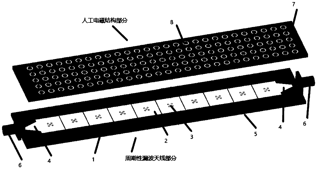
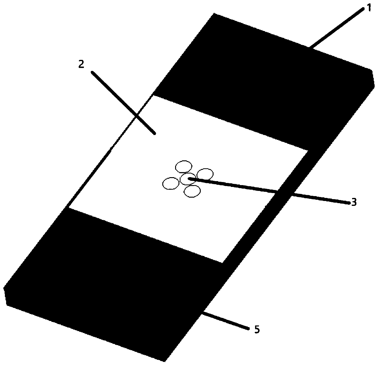
[0027] see Figure 1-2 , which is a structural block diagram of a high-gain beam scanning antenna disclosed by the present invention based on a composite left-handed transmission line. The antenna includes two parts: a periodic leaky-wave antenna and an artificial electromagnetic structure. The periodic leaky-wave antenna includes a Rogers5880 substrate (1) and a first circuit layer and a second circuit layer respectively arranged on both sides of the substrate, the first circuit layer is provided with at least a radiation patch (2) and a microstrip gradient feed patch (4), and the second circuit layer At least the ground (5) is provided, and the radiation patch (2) and the ground are connected by a through hole (3); the artificial electromagnetic structure includes an FR4 substrate (7) and a metal ring array (8) arranged on the subs...


PUM

PropertyMeasurementUnit
impedanceaaaaaaaaaa
radiusaaaaaaaaaa
radiusaaaaaaaaaa

Abstract

The invention discloses a high-gain beam scanning antenna based on a composite left-right hand transmission line. The antenna is composed of a periodic leaky wave antenna and an artificial electromagnetic structure, wherein the periodic leaky wave antenna is composed of a radiation patch, a through hole, a ground, a coaxial feeding part and a Rogers 5880 substrate; the artificial electromagnetic structure is composed of an annular patch array and an FR4 substrate. The S11 of the periodic leaky wave antenna is less than -10dB in the range of 4-6 Ghz, the maximum gain reaches 12.47 dBi, and thescanning range can reach -60 to +60. By loading the artificial electromagnetic structure on the periodic leaky wave antenna, the gain is increased by about 2 dB without changing the scanning range. The antenna of the invention has good application value in a radar system.

Description

technical field [0001] The invention belongs to the technical field of antennas, and specifically relates to a high-gain beam scanning antenna based on a composite left-handed transmission line, based on a CRLH-TL (composite left-handed material transmission line) unit structure and a loaded artificial electromagnetic structure to form a beam scanning with high gain and wide beam scanning range antenna. Background technique [0002] Leaky wave antennas (LWAs) are gaining popularity due to their low profile, narrow beam, simple feeder, and inherent beam scanning capability. Leaky-wave antennas with periodic structures can radiate high-order spatial harmonic electromagnetic power and have a series of advantages such as low loss, flexible radiation characteristics, etc. However, due to the limitation of the aperture stop band, without causing significant gain loss , it is a challenge to realize the lateral radiation of LWA. At present, there are many studies on the use of arti...

Claims


Application Information

Patent Timeline
Patent Type & Authority Applications(China)
IPC IPC(8): H01Q1/36H01Q1/38H01Q1/50H01Q13/08
CPCH01Q1/36H01Q1/38H01Q1/50H01Q13/08
Inventor 程知群周伟伟刘国华
Owner HANGZHOU DIANZI UNIV FUYANG ELECTRONIC INFORMATION RES INST CO LTD
Learn More