Microscope image scanning control method and device and computer storage medium
A technology of image scanning and control method, applied in the microscope field
- Summary
- Abstract
- Description
- Claims
- Application Information
AI Technical Summary
Problems solved by technology
Method used
Image
Examples
Embodiment 1
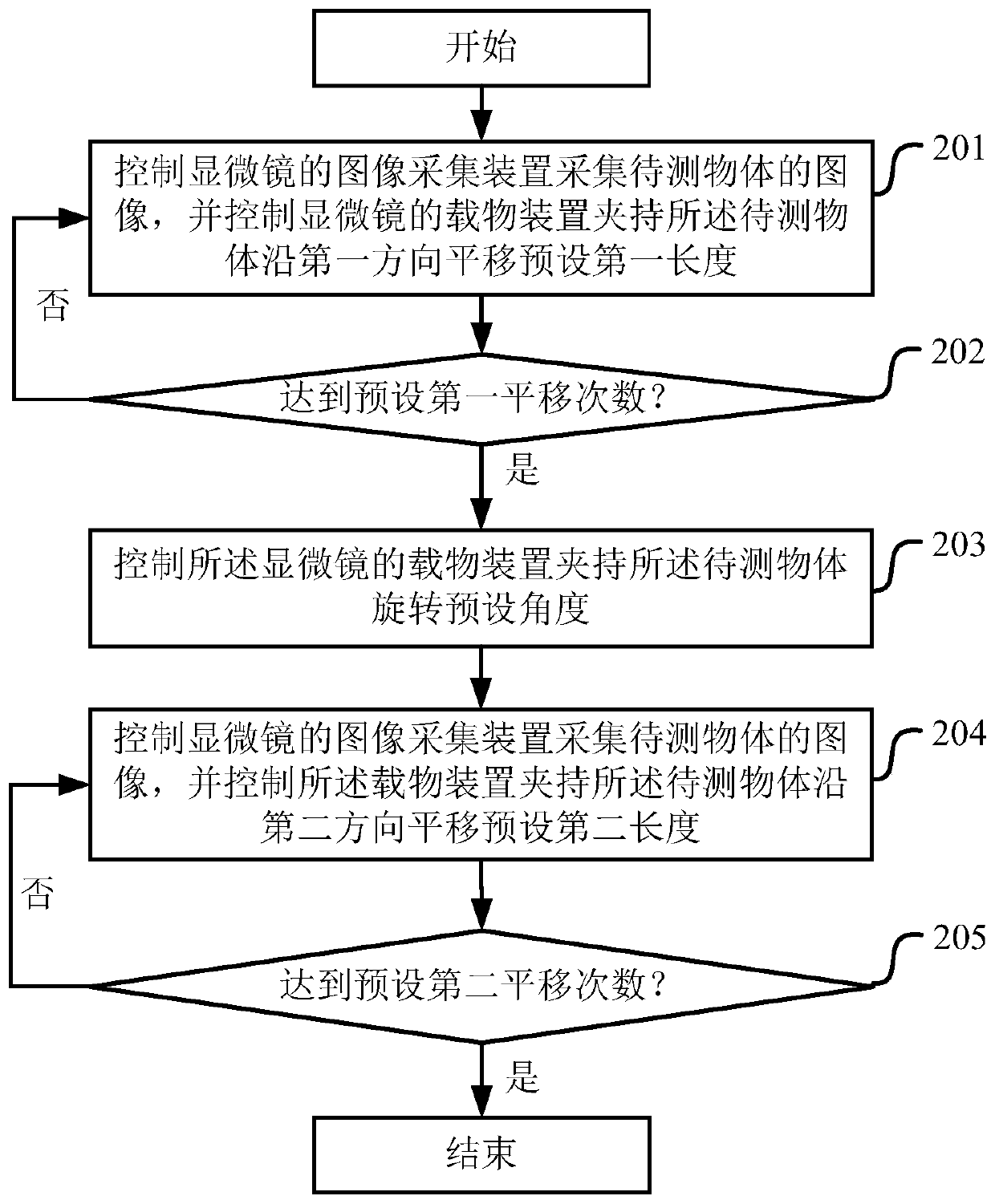
[0046] figure 2 A schematic flow chart showing the implementation of the microscope image scanning control method in Embodiment 1 of the present application is shown.
[0047] As shown in the figure, the microscope image scanning control method includes:
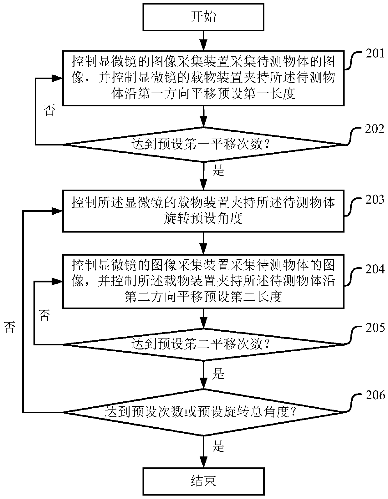
[0048] Step 201, controlling the image acquisition device of the microscope to collect an image of the object to be measured, and controlling the object loading device of the microscope to clamp the object to be measured and translate along a first direction to a preset first length;
[0049] Step 202, repeatedly execute step 201 until the preset first number of times of translation is reached;
[0050] Step 203, controlling the object-carrying device of the microscope to clamp the object to be measured to rotate at a preset angle;
[0051] Step 204, controlling the image acquisition device of the microscope to acquire an image of the object to be measured, and controlling the object carrying device to clamp the object to...
Embodiment 2
[0146] Based on the same inventive concept, an embodiment of the present application provides a microscope image scanning control device. The principle of solving technical problems of the device is similar to that of a microscope image scanning control method, and the repetition will not be repeated.
[0147] Figure 9 A schematic structural diagram of the microscope image scanning control device in Embodiment 2 of the present application is shown.
[0148] As shown in the figure, the microscope image scanning control device includes:
[0149] The first control module 901 is used to control the image acquisition device of the microscope to acquire the image of the object to be measured;
[0150] The second control module 902 is used to control the object-carrying device of the microscope to clamp the object to be measured and translate the preset first length along the first direction each time until reaching the preset first number of times of translation;
[0151] The thi...
Embodiment 3
[0168] Based on the same inventive concept, an embodiment of the present application further provides a computer storage medium, which will be described below.
[0169] The computer storage medium stores a computer program thereon, and when the computer program is executed by a processor, the steps of the microscope image scanning control method as described in the first embodiment are implemented.
[0170] Using the computer storage medium provided in the embodiment of the present application, it is possible to control the stage to translate the object to be measured in the first direction or the second direction, or to rotate the preset angle after each collection of the current position image of the object to be measured , and then image acquisition after changing the position to realize multi-dimensional observation or image scanning of the object to be measured, that is, the application can realize multi-degree-of-freedom microscope image scanning.
PUM
 Abstract
Description
Claims
Application Information
 - R&D Engineer
- R&D Manager
- IP Professional
- Industry Leading Data Capabilities
- Powerful AI technology
- Patent DNA Extraction
Browse by: Latest US Patents, China's latest patents, Technical Efficacy Thesaurus, Application Domain, Technology Topic, Popular Technical Reports.
© 2024 PatSnap. All rights reserved.Legal|Privacy policy|Modern Slavery Act Transparency Statement|Sitemap|About US| Contact US: help@patsnap.com


