Threading plate bottoming device of flat knitting machine

A threading board and threading technology, applied in textiles and papermaking, weft knitting, knitting, etc., can solve the problems of inability to block the calculation of the wire conveying length, waste of resources, defective products, etc., and reduce the cost of weaving and labor. simple effect

Pending Publication Date: 2020-02-28
NINGBO CIXING
View PDF1 Cites 5 Cited by
  • Summary
  • Abstract
  • Description
  • Claims
  • Application Information

AI Technical Summary

Problems solved by technology

This makes it necessary to set multiple rows of needle grooves on the lifting plate, and to set curved guide holes on the side, which is difficult to process and easily affects the machining accuracy, so that the guide holes and the pinholes of the lifting needles cannot be at the same level, resulting in defects products, wasting resources and increasing production costs
[0006] At the same time, the above-mentioned device cannot calculate the conveying length of the blocking wire, and cannot accurately judge whether the blocking wire has passed through all the starting needles, and it is easy for the blocking wire to not completely pass through all the starting needles, causing the coils on the starting needles to fall off , or the blocking wire is conveyed too long, so that it is separated from the wire feeding mechanism and fails

Method used


Image

  • Threading plate bottoming device of flat knitting machine
  • Threading plate bottoming device of flat knitting machine
  • Threading plate bottoming device of flat knitting machine

Examples


Embodiment Construction

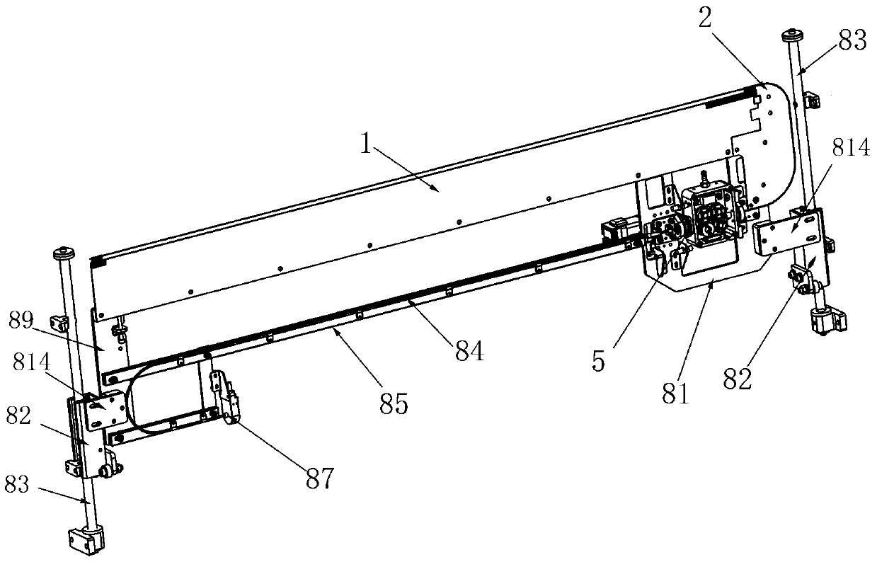
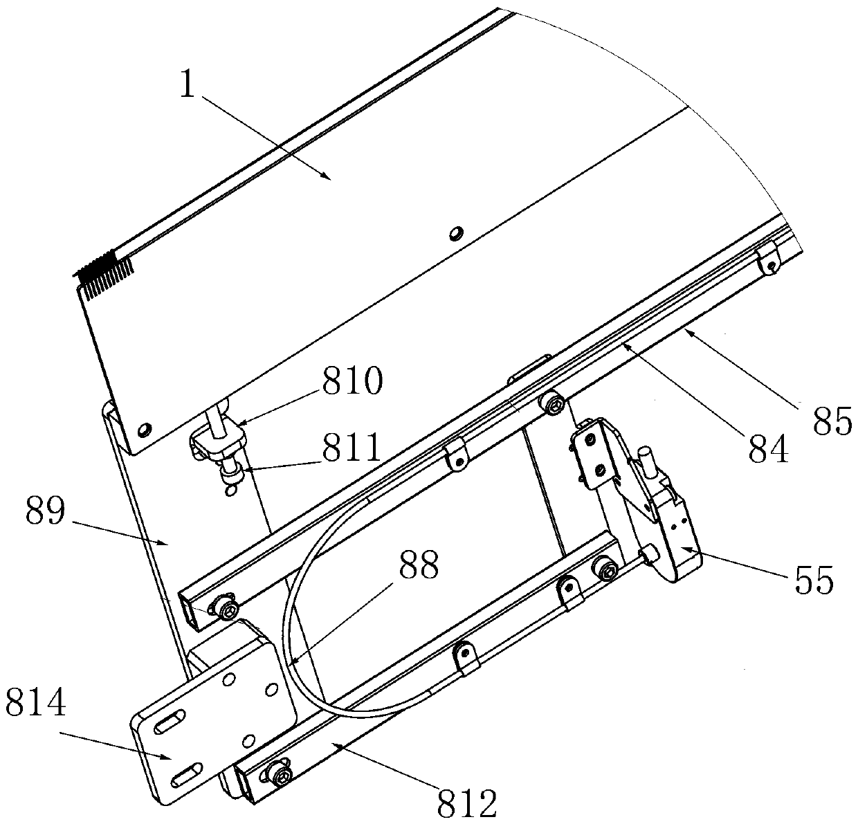
[0052] See attached picture. The lifting device described in this embodiment includes a threading plate assembly, a steel wire conveying assembly and a steel wire limiting assembly. The transmission and rotation of the steel wire is accomplished by the steel wire transmission assembly.

[0053] The threading plate assembly includes the threading plate 1, the lead plate 2 and the slotted needle plate connecting rod 3, the two ends of the threading plate assembly are installed on the left fixed plate 89 and the right fixed plate 81 respectively, and the lifting mechanism includes a linear bearing sleeve 82, a slide bar 83 and the lifting motor, the linear bearing sleeve 82 is installed on the slide bar 83, the lifting motor drives the linear bearing sleeve 82 to slide up and down along the slide bar 83, the left side fixed plate 89 and the right side fixed plate 81 are respectively installed on two sides by a connecting plate 814. On the linear bearing sleeve 82 on the side, th...


PUM


Abstract

The invention discloses a threading plate bottoming device of a flat knitting machine. The threading plate bottoming device of the flat knitting machine comprises a threading plate assembly, a steelwire and a steel wire conveying assembly, and further comprises a steel wire pipe, wherein the threading plate assembly is formed by clamping and fixing a threading plate and a wire guiding plate; thethreading plate is provided with a row of bottoming needles; a threading hole is formed in the head of each bottoming needle; steel wire grooves are formed in the edges of the wire guiding plate; thesteel wire conveying assembly comprises a wire feeding motor and a gear box, a wire feeding wheel and a wire pressing wheel which are movably matched with the wire feeding motor are arranged in the gear box, and two sides of the gear box are respectively provided with sleeves for the steel wires to pass through; sensors are separately arranged at two ends of the steel wire pipe; the steel wire slides along the steel wire pipe, the gear box and the steel wire grooves of the wire guiding plate, can outwards slide relative to the steel wire grooves, and penetrates through the threading holes ofthe bottoming needle. The structure is simple, a woven piece can be completely pulled down under the states of no bottoming fabric and no bottoming tissues, so that no waste yarn is directly taken outof any woven piece, and the weaving cost and the labor cost are greatly reduced.

Description

technical field [0001] The invention belongs to the technical field of knitting machines, in particular to a threading plate lifting device for a flat knitting machine. Background technique [0002] Because there is a certain distance between the mouth of the needle bed and the traction device in the flat knitting machine, that is to say, it is impossible for the woven piece to be clamped by the traction device immediately when it is woven. The woven piece under weaving (that is, the woven piece not clamped by the high roller) is uneven due to the lack of uniform traction, which affects the overall weaving effect of the woven piece, that is, only in the traction state can the woven fabric be smoothly The pieces are woven. Therefore, before entering the formal weaving of the knitted piece, it is first necessary to weave a starting fabric with a length of about 25-35mm. After the starting fabric is clamped by the high roller under the needle bed mouth, the knitted piece can o...

Claims


Application Information

Patent Timeline
IPC IPC(8): D04B15/90D04B15/96
CPCD04B15/90D04B15/96
Inventor 孙平范徐卫东李立军胡跃勇郑文玉
Owner NINGBO CIXING
Why Eureka
Try Eureka