
Yarn guiding device for spinning machine

A yarn guide device and mechanical technology, applied in textiles and papermaking, etc., can solve the problems of difficulty in matching the yarn drawing speed and the yarn swallowing speed, affecting the quality of yarn plying, blocking the yarn guide device, etc., so as to achieve the yarn swallowing speed. Consistent, blocking prevention, consistent yarn swallowing speed

Active Publication Date: 2020-11-03
安徽双盈纺织有限公司
View PDF13 Cites 0 Cited by
  • Summary
  • Abstract
  • Description
  • Claims
  • Application Information

AI Technical Summary

Problems solved by technology

[0003] The purpose of the present invention is to provide a yarn guide device for spinning machinery to solve the problem that it is difficult to keep the matching between the yarn drawing speed and the yarn swallowing speed proposed in the above background technology, thereby affecting the stranding quality of the yarn and the blocking of the yarn guide device

Method used


Image

  • Yarn guiding device for spinning machine
  • Yarn guiding device for spinning machine
  • Yarn guiding device for spinning machine

Examples


Embodiment 1

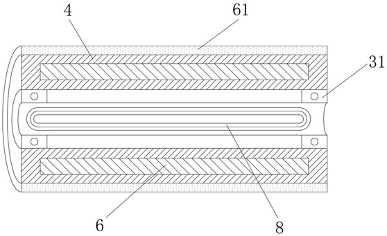
[0026] see Figure 1-3 , the present embodiment provides a yarn guide device for spinning machinery, including a fixed box 1 for installing the yarn guide equipment, material holes 2 are opened on both sides of the fixed box 1 away from each other, and the fixed box 1 is far away from the material hole 2 Both sides are equipped with freely rotatable rollers 4 through the rotating shaft 3. There are four rollers 4, and the four rollers 4 are divided into extraction groups 41 and speed change groups 42 in the same horizontal direction. The roller 4 is arranged along the vertical direction where the fixed box 1 is located.

[0027] The two ends outer walls of rotating shaft 3 are all fixed with bearing 31, and the outer wall of bearing 31 is fixed with the inwall of roller 4, and one end of rotating shaft 3 is fixed with the inwall of fixed box 1, and rotating shaft 3 is hollow cylinder type.

[0028] The extraction group 41 and the speed change group 42 are bonded with a coil 8...

Embodiment 2

[0039] see figure 1 On the basis of Embodiment 1, a further improvement is made: the bottom side of the material hole 2 is provided with a movable groove 21, and a freely rotatable roller shaft 22 is installed between the two sides of the movable groove 21 along the direction of the roller 4, The roller shaft 22 is made of ceramic material. Through the ceramic roller shaft 22, the friction force between the yarn and the material hole 2 can be reduced, the loss of kinetic energy of the motor 71 by the friction force can be avoided, and the direct contact between the yarn and the material hole 2 can be avoided. When excessive hairiness is produced, the situation that affects the quality of yarn strands occurs.


PUM


Abstract

The invention discloses a yarn guide device of a spinning machine. The yarn guide device comprises a fixing box used for mounting a yarn guide unit; two sides, far away from each other, of the fixingbox are provided with material holes respectively, and the two sides, far away from the material holes, of the fixing box are respectively fitted with freely rotatable rollers through rotating shafts;bearings are fixed on the outer walls of the two ends of each rotating shaft; coils are adhered to the inner walls of the rollers, close to the bottom of the fixing box, of an extraction set and a speed change set; a meter head is connected between two ends of each wire far away from the coils; an output end of every meter head is connected with a single chip microcomputer; a magnet is fixed inside each roller; a gear is fixed at one end, far away from the inner wall of the fixing box, of the roller, close to the top of the fixing box, of the speed change set; a power wheel is fixed on a power output shaft of a motor; the single chip microcomputer is connected with the motor through a wire; a movement groove is formed in the bottom of each material hole; and a roller shaft is mounted in each movement groove. By using the above devices together, it is possible to keep a yarn drawing speed consistent to a yarn feeding speed, and to avoid the influence on yarn stranding quality and prevent the yarn guide device from being blocked.

Description

technical field [0001] The invention relates to the related technical field of spinning production, in particular to a yarn guiding device of a spinning machine. Background technique [0002] In the production process of yarn piling, the yarn needs to be extracted from the yarn bobbin. During the extraction process, the speed of yarn extraction and the speed of yarn swallowing by the twisting machine are often not consistent, which easily leads to yarn The speed of extraction cannot meet the supply demand of the twisting machine, or the speed of yarn extraction is greater than the speed of the twisting machine, the above two situations are likely to cause yarn breakage, which will affect the quality of yarn stranding, and lead to The blocking of the yarn device, so there is an urgent need for a yarn guide device that can keep the yarn drawing speed and the yarn swallowing speed synchronized at all times. Contents of the invention [0003] The purpose of the present invent...

Claims


Application Information

Patent Timeline
Patent Type & Authority Patents(China)
IPC IPC(8): D01H13/04D01H13/32
CPCD01H13/04D01H13/32
Inventor 刘化杰刘云雷李小辉
Owner 安徽双盈纺织有限公司
Learn More