Rigid anti-swing lifting device suitable for crane

A crane and rigid technology, applied in the direction of cranes, trolley cranes, hoisting equipment braking devices, etc., can solve the problems of difficult to solve the swaying problem, and achieve the effect of saving time and improving efficiency.

Active Publication Date: 2020-02-28
TAIYUAN UNIVERSITY OF SCIENCE AND TECHNOLOGY
View PDF7 Cites 6 Cited by
  • Summary
  • Abstract
  • Description
  • Claims
  • Application Information

AI Technical Summary

Problems solved by technology

[0004] At present, most cranes use steel wire ropes to realize their functions, but the steel wire ropes are flexible structures, and the problem of swinging is difficult to solve

Method used


Image

  • Rigid anti-swing lifting device suitable for crane
  • Rigid anti-swing lifting device suitable for crane
  • Rigid anti-swing lifting device suitable for crane

Examples


Embodiment

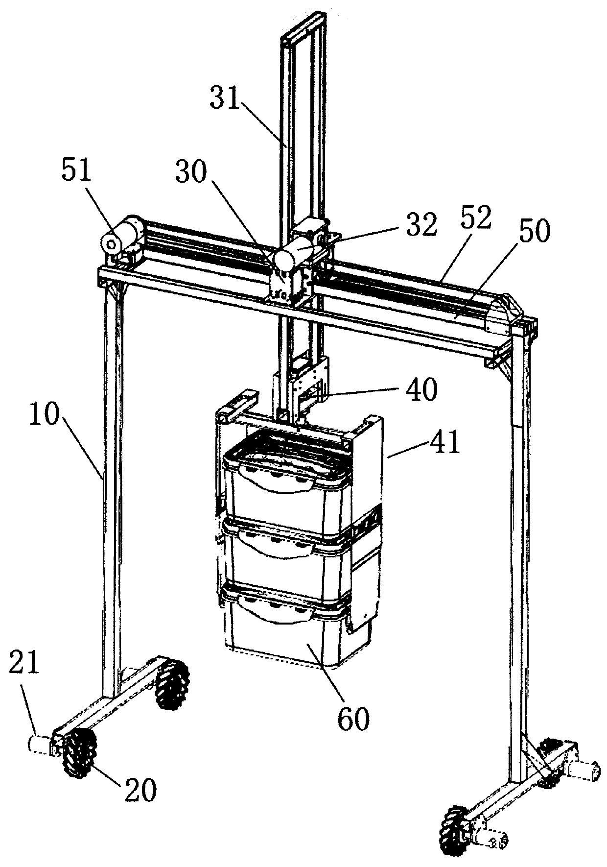
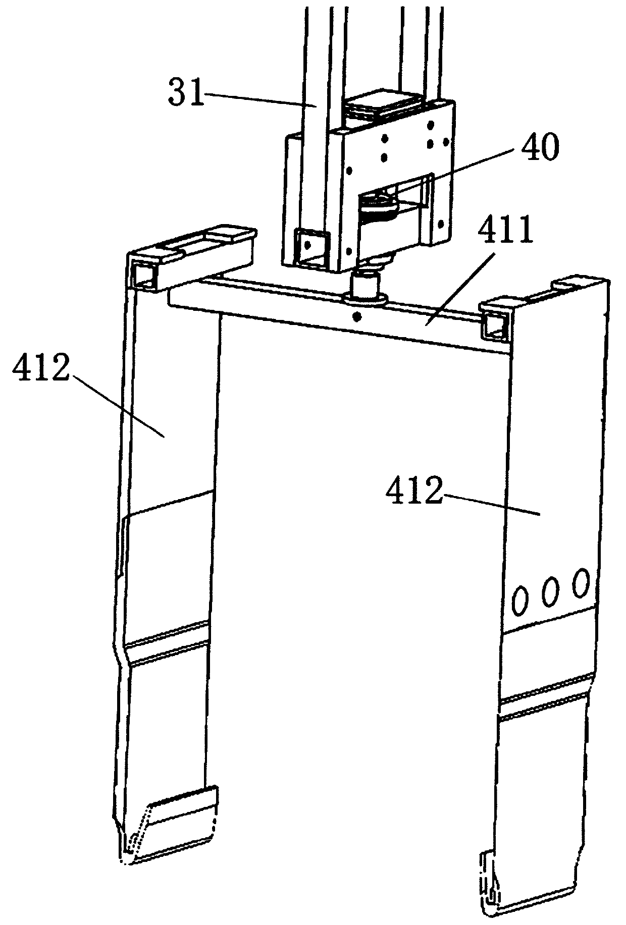
[0037] see Figure 1-6 As shown, a rigid anti-swing lifting device suitable for a crane includes a portal stabilizer 10 on which a traveling mechanism, a lifting mechanism, a translation mechanism, a grabbing mechanism, and a control module are arranged.

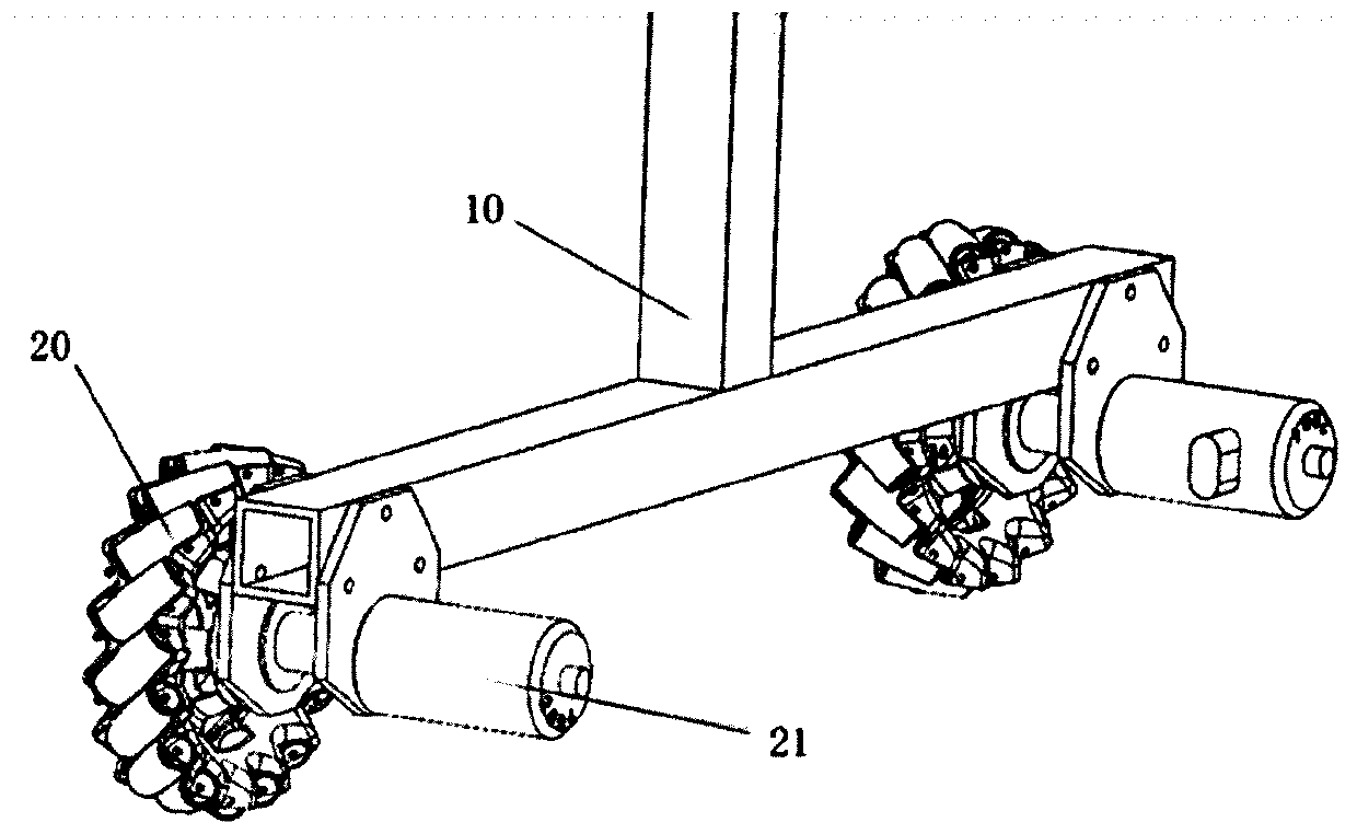
[0038] The traveling mechanism includes several mecanum wheels 20 and traveling motors 21 fixedly arranged at the bottom of the gantry stabilizer 10 , and each mecanum wheel 20 is driven and controlled by a corresponding traveling motor 21 to move in all directions.

[0039] Lifting mechanism comprises sliding seat 30, lifting frame 31, lifting motor 32, wire wheel 33, steel wire rope 34; Lifting frame 31 vertically passes sliding seat 30; Slide seat 30 is assembled by several fiberglass boards. Several spacer bearings 301 are arranged around the side wall of the lifting frame 31 in the slide seat 30, and several spacer bearings 301 are mounted on the slide seat 30 by thin shaft clearance; The walls are slidingly connected,...


PUM


Abstract

The invention provides a rigid anti-swing lifting device suitable for a crane. The rigid anti-swing lifting device is composed of a traveling mechanism, a lifting mechanism, a translation mechanism, acontrol module and a grabbing mechanism; the traveling mechanism utilizes the Mecanum wheel for omni-directional movement, and functions of free rotation, translation, in-situ turning and the like are achieved; the lifting mechanism realizes the anti-swing function through a lifting frame and a clamp, and can maximize the stability and accuracy of guaranteeing the lifting and placement of the goods; the translation mechanism is composed of a translation motor, a horizontal synchronous belt and a sliding seat, and the horizontal synchronous belt can achieve precise translation control of the sliding seat; the control module is mainly used for realizing the flexible displacement of the whole vehicle and the angle control of the grabbing mechanism by using the stm32 integrated board, and precise work of the hoisting and translation mechanism is controlled through the external direct-current driver; the grabbing mechanism is composed of a steering engine and a clamp, so that the clamp canrealize 360-degree steering, and the crossing obstacle is more rapid.

Description

technical field [0001] The invention relates to the technical field of engineering machinery, in particular to a rigid anti-swing lifting device suitable for cranes. Background technique [0002] Gantry crane is a deformation of bridge crane, also called gantry crane. It is mainly used for loading and unloading operations of outdoor cargo yards, stockyard cargoes, and bulk cargoes. Gantry cranes have the characteristics of high site utilization, large operating range, wide adaptability, and strong versatility, and are widely used in port freight yards. Its metal structure is like a door-shaped frame. Two legs are installed under the main beam, which can directly walk on the track on the ground. The two ends of the main beam can have outrigger cantilever beams. [0003] Gantry cranes are developed with the development of the port industry. In 1890, for the first time, a fixed rotatable jib crane with a constant amplitude was installed on the running half-gantry crane acros...

Claims


Application Information

Patent Timeline
Patent Type & Authority Applications(China)
IPC IPC(8): B66C1/30B66C5/02B66C13/06B66C13/08B66C19/00B66D1/12
CPCB66C19/00B66C13/06B66C5/02B66C1/30B66D1/12B66C13/085
Inventor 周利东贾志鹏马红滨李煊俊韩亮韦建辉曹雪芹陈向辉白纯钢霍鹏亮曾雪林何世康杨秀峰
Owner TAIYUAN UNIVERSITY OF SCIENCE AND TECHNOLOGY
Why Eureka
Try Eureka