Shore power cable management device

A management device and electric cable technology, which is applied in the field of shore power cable management device, can solve problems such as potential safety hazards, and achieve the effects of avoiding friction, reducing leakage, and ensuring cable tension

Active Publication Date: 2020-02-28
XJ POWER CO LTD +2
View PDF7 Cites 2 Cited by
  • Summary
  • Abstract
  • Description
  • Claims
  • Application Information

AI Technical Summary

Problems solved by technology

[0005] The purpose of the present invention is to provide a shore power cable management device, which is used to solve the problem of potential safety hazards in the use of the shore power cable intelligent management system in the prior art

Method used


Image

  • Shore power cable management device
  • Shore power cable management device
  • Shore power cable management device

Examples


Embodiment 1

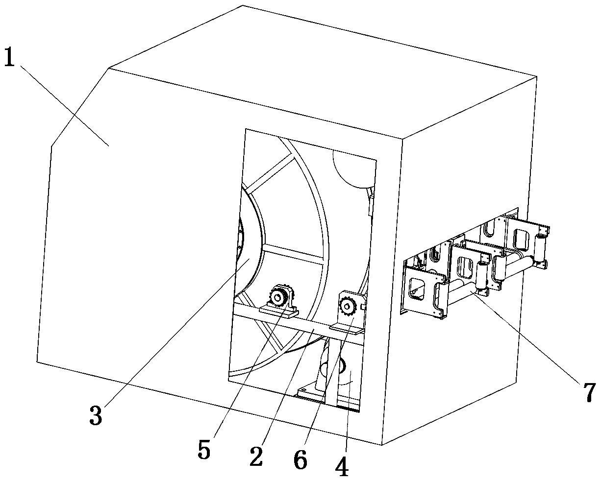
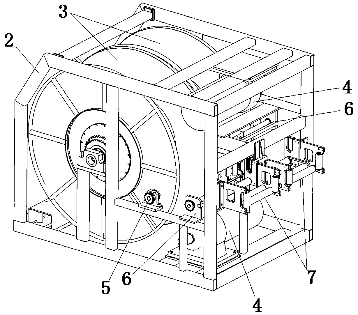
[0035] Such as figure 1 and figure 2 As shown, the shore power cable management device includes a housing 1, a mounting frame 2 and two sets of take-up and release systems. The installation basis of the pay-off system; both take-up and pay-off systems include a reel 3, a drive motor 4, an intermediate transmission mechanism 5, an automatic wire-discharging mechanism 6 and a pay-off assist mechanism 7.

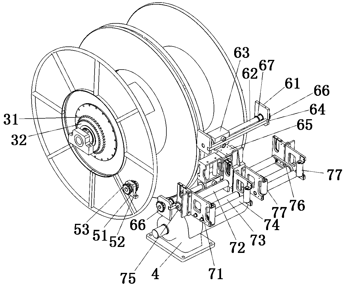
[0036] Such as Figure 1-Figure 5As shown, the reel 3 is rotatably installed on the mounting frame 2, the driving motor 4 is fixedly installed on the mounting frame 2, the reel 2 is equipped with a first reel sprocket 31, and the first reel sprocket 31 and the reel 3 The axes of rotation are collinear, and the drive motor 4 drives the reel 3 to rotate through the first reel sprocket 31 and related chains (not shown in the figure); the second reel sprocket 32 ​​is also installed on the reel 3, and the second The drum sprocket 32 ​​is likewise in line with the axis of rotatio...

Embodiment 2

[0047] The difference from Embodiment 1 is that the driving roller sleeve in Embodiment 2 is fixed to the driving central shaft, and there is no one-way clutch between the two, but the sprocket matched with the power-assisted chain on the driving central shaft and A one-way clutch is set between the active central shafts. The one-way clutch is combined when the reel is unwound and disconnected when the reel is taken up. In this way, it can also ensure the connection between the pay-off assist mechanism and the reel when the reel is unwound. The cable is under tension.

Embodiment 3

[0049] The difference from Example 1 is that in this Example 3, no active central shaft is set, and the active roller cover is replaced by a solid active solid roller. The power-assisted chain drives the active solid roller to rotate, and a one-way clutch is set between the sprocket on the active solid roller and the active solid roller. The one-way clutch is combined when the reel is unwound and disconnected when the reel is taken up; the active solid roller The distance between the driven roller sleeve and the driven roller sleeve ensures that the two can clamp the cable, which can also ensure that the cable between the pay-off assist mechanism and the reel is in a tensioned state when the reel is unwound.

[0050] In each of the above-mentioned embodiments, between the drive motor and the reel, between the reel and the intermediate transmission mechanism, between the intermediate transmission mechanism and the automatic wire unwinding mechanism, between the automatic wire un...


PUM


Abstract

The invention relates to a shore power cable management device. The shore power cable management device comprises a mounting frame, a coiling block, a driving motor and a paying-off power-assisting mechanism, the coiling block is rotationally assembled on the mounting frame, and the driving motor is used for driving the coiling block to rotate; the paying-off power-assisting mechanism comprises adriving roller and a driven roller which are parallelly arranged in a spaced mode, and a clamping space used for clamping a cable is arranged between the driving roller and the driven roller; the driving roller is in transmission connection with the coiling block, a engaging and disengaging device is arranged on a transmission path of the driving roller and the coiling block, and the engaging anddisengaging device is disengaged during taking-up of the coiling block and engaged during paying-off of the coiling block; and during paying-off, the cable passes through the clamping space between the driving roller and the driven roller and is clamped by the driving roller and the driven roller for paying-off, the clamping paying-off speed of the driving roller and the driven roller is greater than the paying-off speed of the coiling block, and thus the cable between the coiling block and the paying-off power-assisting mechanism is kept to be tensioned. The shore power cable management device is used for solving the problem that an existing shore power cable management system has potential safety hazards during using.

Description

technical field [0001] The invention relates to a shore power cable management device. Background technique [0002] When the ship is docked, the shore power equipment is required to supply power to the ship's electrical equipment. The ship and the shore power equipment are connected by cables, and the retraction and storage of the cables are generally realized by the shore power management device. [0003] For example, a shore power cable intelligent management system recorded in the invention patent application document with the application publication number CN109179089A is used to retract and store cables. The system includes a frame body and two sets of winding units located in the frame body. , each winding unit includes a drum for winding the cable, a motor for driving the drum to rotate, and a cable puller for the cable; when the wire is taken up, the motor drives the drum to rotate, and the cable is pulled to be wound on the drum At the same time, the cable guide r...

Claims


Application Information

Patent Timeline
IPC IPC(8): B65H75/38B65H75/44
CPCB65H75/38B65H75/44B65H75/4405B65H75/4481B65H75/4486B65H2701/34
Inventor 刘辉勇甘江华季建维侯泽芳张超锋万煜新王政常延杰孙国厂贾红杰宋东阳蔺深伟杨亚培刘斌邢红伟
Owner XJ POWER CO LTD
Why Eureka
Try Eureka