
Winding mechanism and winding device

A technology of winding mechanism and driving mechanism, which is applied in the direction of transportation and packaging, conveying filamentous materials, thin material processing, etc., can solve the problem of uneven winding of printing materials, and achieve the effect of ensuring neat winding

Pending Publication Date: 2020-02-28
广东三绿科技有限公司
View PDF0 Cites 5 Cited by
  • Summary
  • Abstract
  • Description
  • Claims
  • Application Information

AI Technical Summary

Problems solved by technology

However, since the wire reel has a certain width, and the wire diameter of the printing material is thinner than that of the wire reel, the position of the wire reel is fixed during the winding process, and the printing materials will be concentrated on a certain position of the wire reel, such as the wire The left, middle or right side of the reel, resulting in uneven winding of the printed material

Method used


Image

  • Winding mechanism and winding device
  • Winding mechanism and winding device
  • Winding mechanism and winding device

Examples


Embodiment Construction

[0024] The embodiments of the present invention are described in detail below. Examples of the embodiments are shown in the accompanying drawings, in which the same or similar reference numerals indicate the same or similar elements or elements with the same or similar functions. The embodiments described below with reference to the drawings are exemplary, and are only used to explain the present invention, but should not be understood as limiting the present invention.

[0025] In the description of the present invention, unless otherwise clearly defined, terms such as setting, installation, and connection should be understood in a broad sense, and those skilled in the art can reasonably determine the specific meaning of the above terms in the present invention in combination with the specific content of the technical solution.

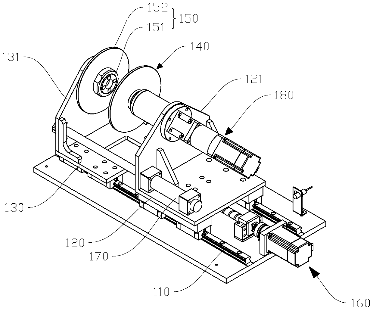
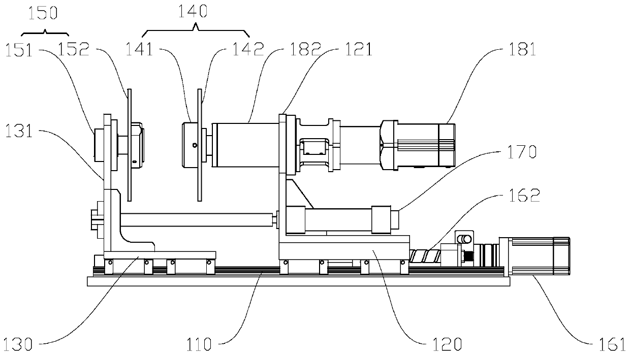
[0026] Please refer to figure 1 with figure 2 , This embodiment discloses a winding mechanism, including a sliding rail 110, a first sliding block 120, a...


PUM


Abstract

The invention discloses a winding mechanism and a winding device. The winding mechanism comprises a sliding rail, a first sliding block, a second sliding block, a first wire coil mounting frame and asecond wire coil mounting frame, wherein the first sliding block is mounted on the sliding rail and is connected with a first driving mechanism; the second sliding block is mounted on the sliding railand is connected with the first sliding block through a telescopic mechanism; the first wire coil mounting frame is mounted on the first sliding block and is connected with a second driving mechanism; the second wire coil mounting frame is mounted on the second sliding block and is used for being matched with the first wire coil mounting frame to clamp a wire coil; and the first sliding block andthe second sliding block can move along the sliding rail in the winding process. When the winding mechanism is used, the first wire coil mounting frame and the second wire coil mounting frame are matched to clamp the wire coil, the first driving mechanism drives the first sliding block and the second sliding block to move along the sliding rail, the wire coil moves along the sliding rail along with the first sliding block and the second sliding block, so that a printing material can be smoothly transited from one end of the wire coil to the other end of the wire coil in the winding process, and the printing material can be wound in order.

Description

Technical field [0001] The invention relates to the technical field of 3D printing consumables, in particular to a winding mechanism and a winding device. Background technique [0002] The printing materials used by 3D printers are generally linear. During production, the printing material needs to be wound on the wire reel. At present, the winding method of the printing material usually uses a motor to drive the reel to rotate to realize the winding of the printing material. However, because the spool has a certain width, and the diameter of the printed material is relatively thin compared to the spool, the position of the spool is fixed during the winding process, and the printed material will be concentrated on a certain position of the spool, such as the line The left, middle, or right side of the tray causes uneven winding of the printed material. Summary of the invention [0003] The present invention aims to solve at least one of the technical problems existing in the pri...

Claims


Application Information

Patent Timeline
Patent Type & Authority Applications(China)
IPC IPC(8): B65H59/10B65H57/14B65H54/553B65H54/28B65H63/00B65H54/44
CPCB65H59/10B65H57/14B65H54/553B65H54/2803B65H63/00B65H54/44B65H2701/36
Inventor 彭永明
Owner 广东三绿科技有限公司
Learn More