Lifting trolley

A trolley and lifting platform technology, which can be used in trolleys, motor vehicles, multi-axle trolleys, etc., can solve the problems of labor-intensive, time-consuming and labor-intensive

Inactive Publication Date: 2020-02-28
SUZHOU JINGLAI OPTO CO LTD
View PDF12 Cites 2 Cited by
  • Summary
  • Abstract
  • Description
  • Claims
  • Application Information

AI Technical Summary

Problems solved by technology

[0002] When materials or products are transferred between machines, the materials or products are transferred using a transport trolley. The existing transport trolley can only transport the materials to the side of the machine, and the materials need to

Method used


Image

  • Lifting trolley
  • Lifting trolley
  • Lifting trolley

Examples


Embodiment 1

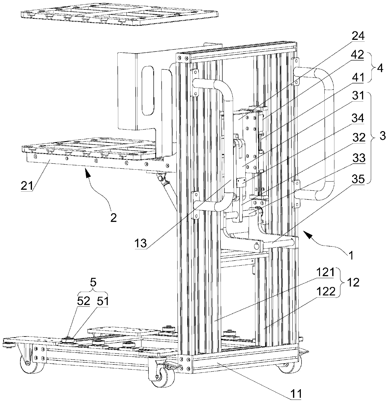
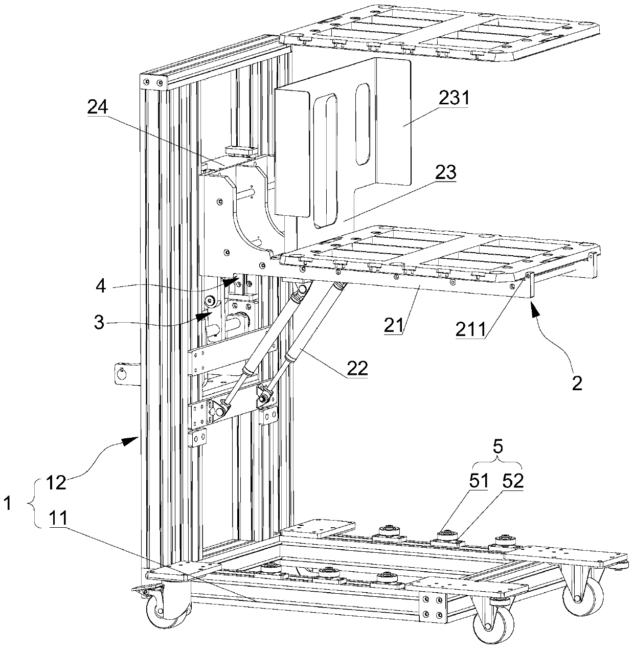
[0047] Such as Figure 1-Figure 4 As shown, this embodiment provides a lifting trolley for docking with the machine platform, transporting to the machine platform and picking and placing products or materials at the machine platform. The lifting trolley includes a bracket 1, a lifting platform assembly 2 and a connecting rod assembly 3, wherein the bracket 1 can move, the lifting platform assembly 2 is slidably arranged on the bracket 1, and the lifting platform assembly 2 can be vertically aligned with the bracket 1. direction to slide back and forth. The connecting rod assembly 3 is respectively connected to the lifting platform assembly 2 and the support 1. When the lifting platform assembly 2 is at the highest point, the connecting rod assembly 3 moves to the limit position and can be kept at the limit position.

[0048] The support 1 is "L" type, and the support 1 includes a mobile support 11 and a support frame 12, and the bottom of the mobile support 11 is rotatably pr...

Embodiment 2

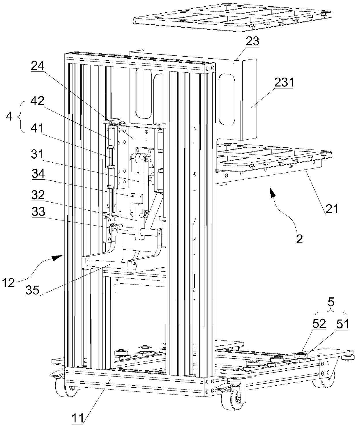
[0060] On the basis of the first embodiment above, the difference from the first embodiment is that the structural form of the connecting rod assembly 3 and the connection relationship with other structural parts are different, as follows, as Figure 5 as shown, Figure 5 Schematic diagram of the lift trolley structure.

[0061] The connecting rod assembly 3 includes a first connecting rod 31, one end of the first connecting rod 31 is hinged with a second connecting rod 32, and the other end is hinged at the lifting stage assembly 2, and the second connecting rod 32 is located above the first connecting rod 31 . The connecting rod assembly 3 also includes a rotating shaft 33, the rotating shaft 33 is horizontally installed on the second connecting rod 32, and its two ends are rotatably connected to the bracket 1, the rotating shaft 33 can drive the second connecting rod 32 to move, and the rotating shaft 33 is arranged on Above the first connecting rod 31.

[0062] In this ...


PUM


Abstract

The invention relates to the technical field of material handling, and discloses a lifting trolley. The lifting trolley comprises a bracket and a connecting rod assembly, wherein the bracket can move,a lifting platform assembly is slidably arranged on the bracket, and the lifting platform assembly can slide back and forth in the vertical direction relative to the bracket; and the connecting rod assembly is correspondingly connected with the lifting platform assembly and the bracket, when the lifting platform assembly is located at the highest point, the connecting rod assembly moves to the limit position, and can be kept at the limit position. The lifting trolley can accurately butt joint a machine platform, place materials on the machine platform, and can take the materials from the machine platform.

Description

technical field [0001] The invention relates to the technical field of material handling, in particular to a lifting trolley. Background technique [0002] When materials or products are transferred between machines, the materials or products are transferred using a transport trolley. The existing transport trolley can only transport the materials to the side of the machine, and the materials need to be placed on the machine by manual handling. . When retrieving the material, it is manually transported to the trolley. This method consumes a lot of labor, and it is necessary to reposition the material when placing it, which is time-consuming and laborious. [0003] Therefore, there is an urgent need for a transport trolley capable of docking with the machine platform and discharging materials to solve the above problems. Contents of the invention [0004] The object of the present invention is to provide a lifting trolley, which can accurately dock with the machine platfo...

Claims


Application Information

Patent Timeline
IPC IPC(8): B62B3/04B62B3/06B62B3/065
CPCB62B3/04B62B3/0618B62B3/0625
Inventor 花红飞
Owner SUZHOU JINGLAI OPTO CO LTD
Why Eureka
Try Eureka